
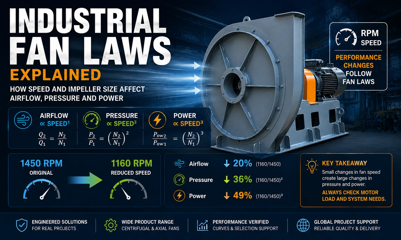
Industrial Fan Laws Explained: How Speed And Impeller Size Affect Airflow, Pressure And Power

Fan laws – also called fan affinity laws – provide a practical way to estimate how an industrial fan may perform when rotational speed, air density or the size of a geometrically similar fan changes. This guide explains the formulas, calculation steps, engineering limits and motor-power risks buyers should check before changing fan speed or frequency.
Get Fan Selection Support Read the Fan Performance Curve Guide
Three Fan Laws for Speed Changes
For the same fan operating with approximately the same gas density and within a stable performance range:
Q₂ = Q₁ × (N₂ / N₁)
Δp₂ = Δp₁ × (N₂ / N₁)²
P₂ = P₁ × (N₂ / N₁)³
Apply these estimates to corresponding points for unchanged fan geometry and approximately unchanged gas density. Compare corresponding points with similar flow coefficients and approximately unchanged efficiency; Reynolds and Mach number effects and mechanical losses may limit these estimates. Actual installed duty still depends on the system curve; allowable speed and motor capacity require verification.
Important: In these equations, power means the fan’s absorbed shaft power at the operating point – not automatically the motor nameplate rating. Motor efficiency, VFD and transmission losses, mechanical losses and suitable operating margin must be reviewed separately. A shaft-power ratio is not a direct guarantee of electrical-input savings.
Engineering caution: Fan laws are screening calculations. They should not replace a tested fan performance curve, motor-power review, mechanical-speed verification or final manufacturer confirmation.
What Are Industrial Fan Laws?
Fan laws are proportional relationships used to predict changes in airflow, pressure and power when one known fan condition is changed to another similar condition. They are widely used for preliminary checks involving fan speed, variable-frequency operation, air density and geometrically similar fan sizes.
The laws do not replace a tested fan curve. They estimate how a known performance point or curve may shift. The actual operating point still depends on the connected duct system, filters, dampers, dust collector, inlet conditions and discharge resistance.
Buyers should therefore use fan-law calculations as an engineering screening tool, then verify the result against the manufacturer’s performance data, motor capacity, mechanical speed limit and actual system requirements.
If you are first reviewing centrifugal fan structure, airflow direction and main components, start with What Is a Centrifugal Fan? before applying fan-law calculations.
Conditions Required Before Applying the Formulas
Fan-law estimates are most useful when the comparison remains physically similar and the fan stays within a stable operating range.
Speed-only comparisons assume the same wheel, casing, clearances and airflow path.
Changes in temperature or altitude require a separate density check.
Do not extrapolate simple proportions through unstable, stall or surge regions.
Confirm wheel, shaft, bearings, transmission and motor limits for the proposed RPM.
Symbols Used in Fan-Law Calculations
| Symbol | Meaning | Typical Units | Selection Note |
|---|---|---|---|
| Q | Volume airflow | m³/h, m³/s, CFM | Keep units consistent between condition 1 and condition 2. |
| Δp | Fan pressure rise | Pa, kPa, in. w.g. | Do not mix static pressure and total pressure in one comparison. |
| N | Rotational speed | rpm | Use actual fan RPM, not only nominal synchronous motor speed. |
| P | Absorbed fan shaft power | kW, hp | Compare with available motor and drive capacity after calculation. |
| D | Characteristic impeller diameter | mm, m, in. | Diameter laws require geometrically similar fan designs. |
| ρ | Gas density | kg/m³ | Affected by temperature, altitude, pressure and gas composition. |
Subscript 1 indicates the known operating condition. Subscript 2 indicates the proposed or calculated condition.
Assume the original values are measured or taken from a valid performance curve at the same gas density.
| Parameter | Original | Calculated | Relative Change |
|---|---|---|---|
| Speed | 1450 rpm | 1160 rpm | −20% |
| Airflow | 20,000 m³/h | 16,000 m³/h | −20% |
| Total pressure | 2,000 Pa | 1,280 Pa | −36% |
| Absorbed shaft power | 18.5 kW | 9.47 kW | −48.8% |
Engineering conclusion: Reducing speed can reduce absorbed power substantially, but the available pressure also falls faster than airflow. The system may no longer overcome filter, duct or process resistance even when the calculated airflow appears acceptable.
Why Increasing Speed Creates a Motor-Power Risk
Worked illustration: 1450 → 1600 rpm. Reuse the assumed starting values above: 20,000 m³/h, 2,000 Pa total pressure and 18.5 kW absorbed shaft power. The speed ratio is 1600 / 1450 = 1.103448. These are teaching values, not a rated QIYUE model or a proposed operating instruction.
Bar lengths compare percentage increases, not absolute quantities. Calculation: multiply the baseline by 1.103448, its square and its cube respectively; rounded only for display.
The larger power increase explains why a modest RPM change deserves a full selection review. It does not mean a 24.86 kW motor is automatically suitable. The illustration assumes unchanged geometry and density, corresponding stable operating points and approximately unchanged efficiency; installed duty still requires the system curve. Technical basis: ASHRAE Handbook, Fans, section 5.
Before increasing fan speed, verify the absorbed-power curve, motor service margin, impeller maximum safe speed, shaft stress, bearing rating, belt or coupling limit, vibration condition, noise and the new operating point. Increasing frequency or changing pulleys without this review can overload the motor or create a mechanical safety risk.
50 Hz, 60 Hz and Variable-Frequency Operation
Electrical frequency affects motor speed, but actual fan RPM also depends on motor poles, slip, drive ratio and VFD settings. Review the actual RPM rather than using frequency alone.
A 20% speed increase is not only a 20% power increase
If actual fan speed rises in the same 50-to-60 ratio:
Approximately 1.20 ×
Approximately 1.44 ×
Approximately 1.728 ×
These are similarity estimates at corresponding operating conditions, not permission to change supply frequency or a guarantee of installed airflow.
A fan selected for 50 Hz operation should not be assumed suitable for 60 Hz operation without reviewing motor power, fan curve and mechanical speed limits.
VFD speed reduction is often useful because absorbed power can fall rapidly. However, the following still require review:
Minimum airflow and pressure, including the boiler, dust-control or ventilation duty.
Low-speed motor cooling; lubrication and resonance; maximum motor frequency and actual fan RPM.
Read Motor Poles, RPM and 50/60 Hz
How Impeller Diameter Changes Fan Performance
For a family of geometrically similar fans operating at the same speed and density, ideal similarity relationships can be used for an initial comparison.
Q ∝ D³N
Δp ∝ ρD²N²
P ∝ ρD⁵N³
D is characteristic impeller diameter, N is actual fan speed, and ρ is gas density. These are similarity relationships for geometrically similar designs at corresponding operating points, not guaranteed performance for arbitrary wheel changes. At equal speed and density, the diameter factors are D³, D² and D⁵ respectively. Do not apply these diameter relationships directly to an impeller trimmed within an unchanged casing.
When an existing wheel is trimmed inside the same casing, outlet width, blade geometry, inlet clearance and casing relationship may not change proportionally. Efficiency and curve shape may also change. Use manufacturer recalculation, revised performance data or testing for the final result.
High Temperature, Altitude and Gas Density
At the same fan speed and volume flow, lower gas density generally reduces the pressure developed and the absorbed power. Hot gas is less dense than normal-temperature air, while altitude also changes air density.
For a simple density comparison at unchanged speed and fan geometry:
Δp₂ = Δp₁ × (ρ₂ / ρ₁)
P₂ = P₁ × (ρ₂ / ρ₁)
Use corresponding operating points and a consistent pressure definition. P here is absorbed shaft power, not motor nameplate rating.
Need a temperature-based density correction example? See how gas temperature changes air density, fan pressure and absorbed power in our detailed engineering guide.
For higher pressure ratios, gas compressibility may require a more advanced calculation rather than the simplest density correction.
Fan Laws Shift the Fan Curve – They Do Not Define the System by Themselves
The actual airflow is determined where the fan curve and the system resistance curve intersect. A calculated 20% airflow increase is not guaranteed if the connected system, damper position, filter condition or inlet arrangement changes the operating point.
Shows the fan’s airflow-pressure performance at a stated speed, diameter and gas condition.
Represents the pressure required to move different airflow rates through ducts, elbows, filters and equipment.
The intersection of the fan curve and system curve is the actual working point that must satisfy the process.
How to Read a Fan Performance Curve Static Pressure vs Total Pressure
Common Fan-Law Calculation Errors
- Mixing static pressure with total pressure in one comparison.
- Using motor nameplate power as though it were absorbed fan shaft power.
- Assuming a 50 Hz to 60 Hz speed increase is safe without motor and mechanical-limit checks.
- Applying ideal diameter similarity to a trimmed wheel without a revised curve.
Where Fan Laws Are Used in Real Projects
The same formulas may support different decisions, but each application has additional process and safety constraints.
Information Needed Before Recalculating Fan Performance
| Required Information | Why It Is Needed | Example |
|---|---|---|
| Existing fan model and curve | Provides the verified starting point. | Model, impeller diameter, curve sheet |
| Current airflow and pressure | Defines the current operating point. | 20,000 m³/h at 2,000 Pa |
| Current and proposed RPM | Determines the speed ratio. | 1450 rpm to 1160 rpm |
| Motor and drive data | Checks overload and transmission limits. | kW, voltage, frequency, belt or coupling |
| Gas temperature and density | Corrects pressure and power for real gas conditions. | 20°C air or 180°C flue gas |
| Target duty point | Confirms whether the recalculated fan meets the process. | Required airflow, pressure and operating time |
Engineering Basics for Fan Selection
Use the fan performance curve guide to identify the actual duty point, then review the required operating conditions in the fan selection process. A fan-law estimate must be checked against the selected model and system resistance.
Frequently Asked Questions About Fan Laws
What are the three basic fan laws?
For the same fan and similar gas condition, airflow changes directly with speed, pressure changes with speed squared, and absorbed shaft power changes with speed cubed.
Does doubling fan speed double airflow?
The ideal airflow estimate doubles, but pressure rises approximately four times and absorbed power approximately eight times. In practice, mechanical limits and motor capacity will usually prevent such a change.
Can a VFD increase industrial fan airflow?
A VFD can increase fan speed only when the motor, fan wheel, shaft, bearings and drive are suitable for the higher RPM and the resulting absorbed power. System resistance must also be checked.
Can a 50 Hz fan run directly at 60 Hz?
It should not be assumed suitable. If actual speed rises by about 20%, the ideal absorbed-power estimate rises by about 72.8%. The motor, performance curve and mechanical speed limit must be reviewed.
Do fan laws apply to centrifugal and axial fans?
The similarity principles are used for both fan types, provided the comparison remains physically similar and the fan operates in a stable performance range.
Are fan laws accurate after trimming an impeller?
They may provide an initial estimate, but trimming an existing wheel inside the same casing is not always geometrically similar. Final performance should be recalculated or verified with manufacturer data.
Why does the site airflow differ from the fan-law calculation?
The actual operating point depends on system resistance, duct leakage, inlet obstructions, filter condition, rotation direction, clearances and mechanical condition. Fan laws do not replace site diagnosis.
Send the existing fan model, curve, airflow, pressure, RPM, motor data, gas temperature and target operating point. QIYUE FAN will review the preliminary calculation and suitable configuration direction.
Send Operating Data Contact by WhatsApp View Product Catalog
QIYUE FAN CO., LTD. · Industrial Fan Manufacturer · Email: sales@qiyuefan.com · WhatsApp: +86 156 5330 5981
Send Your Operating Conditions
Airflow, pressure, gas medium, temperature, voltage and quantity.