
Why Is Fan Airflow Lower Than The Fan Curve After Installation?
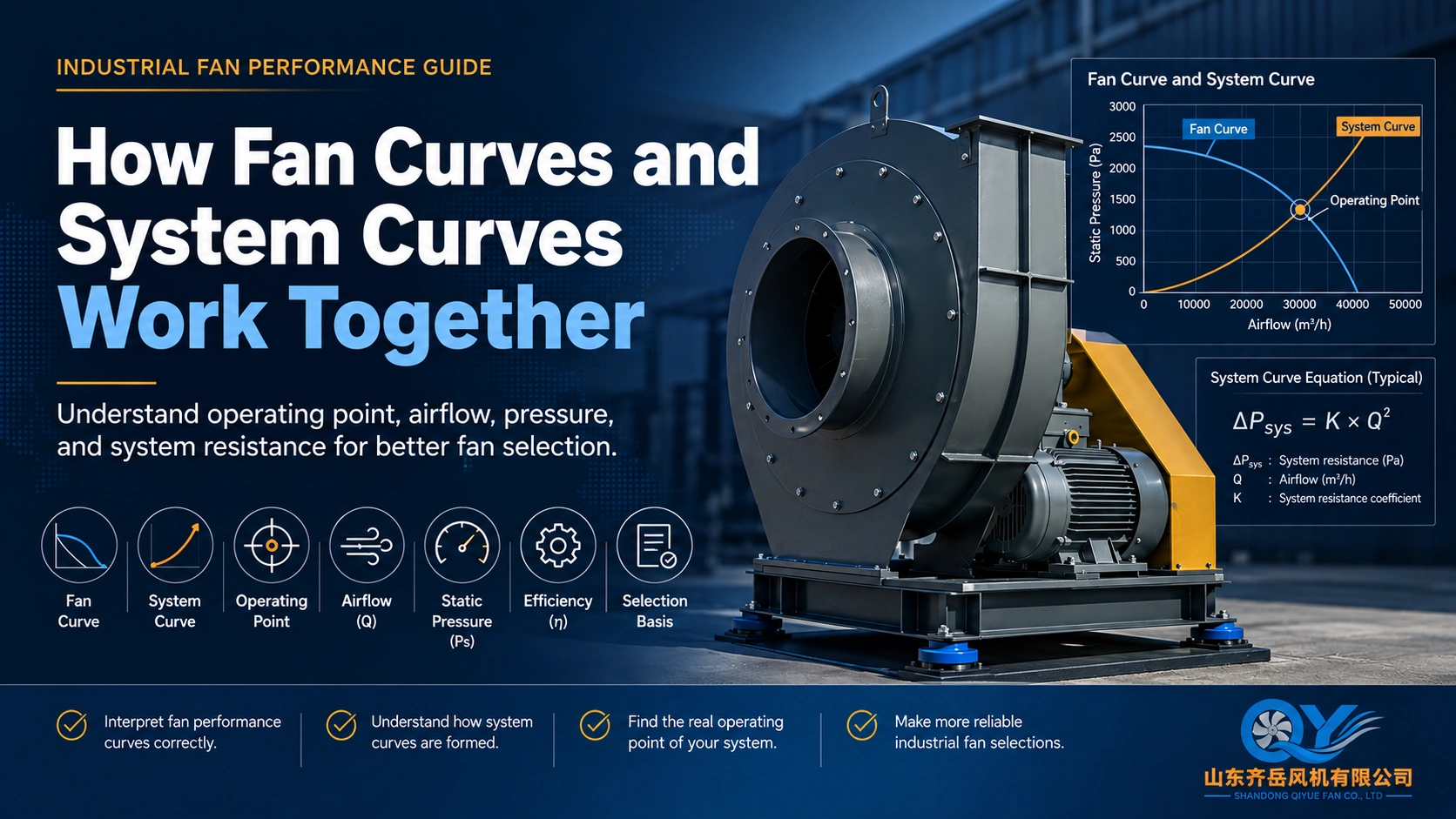
An industrial fan may be correctly selected according to the required airflow and pressure, but after installation the actual airflow can still be lower than expected. This does not automatically mean the fan performance curve is incorrect. In many projects, the real cause is the resistance and airflow condition of the installed system around the fan.
Ducts, elbows, filters, dampers, transitions, silencers, collectors and outlet arrangements all create resistance and influence the real operating point. A fan curve can therefore be correct while the installed airflow is still lower than the original design target.
The Fan Curve and the System Curve Work Together
A fan performance curve describes the relationship between airflow and pressure produced by a fan at a defined speed and operating condition. The air system also has its own pressure-airflow relationship.
As airflow increases, resistance from ducts and system components normally increases. For many fixed duct systems, the pressure loss can be approximated by:
The actual operating point is where the fan curve intersects the system resistance curve. If system resistance changes, the operating point also changes.
A longer duct, an additional filter, a partially closed damper or a poor inlet or outlet arrangement can all move the fan away from the airflow originally expected during selection.
For more background on operating points and performance curves, see How to Read a Fan Performance Curve .
1. Actual System Resistance Is Higher Than Expected
This is one of the most common reasons for insufficient airflow after installation.
During preliminary fan selection, pressure may be based on estimated resistance. The final installed system may later contain additional losses that were not included, or were underestimated.
If these losses are higher than the original pressure basis, the fan does not necessarily have a performance defect. Instead, it operates at a different point on the fan curve.
This is why airflow alone cannot define an industrial fan selection. The required pressure must represent the resistance of the real air path through the complete system.
If the pressure requirement is still unknown, continue with: How to Select an Industrial Fan When Static Pressure Is Unknown .
2. Inlet Conditions Can Create Additional Performance Loss
A fan normally performs best when air approaches the inlet in a relatively uniform condition. Actual installations do not always provide this.
Typical examples include:
- an elbow located immediately before the fan inlet;
- a reducer or transition positioned too close to the fan;
- a wall, structure or process machine restricting inlet airflow;
- a damper positioned directly in front of the inlet;
- strongly uneven airflow entering from one side.
These arrangements can create swirl, turbulence and non-uniform velocity distribution. The impeller then receives the air differently from the controlled condition represented by the normal performance curve.
Installation-related inlet or outlet conditions can create additional losses even when the fan itself is correctly selected.
3. Outlet Arrangement Can Also Reduce Actual Performance
The inlet is not the only area that matters. Air leaving a centrifugal fan also has a specific velocity profile.
Problems can occur when:
- a sharp elbow is installed immediately after the fan outlet;
- an abrupt transition is positioned close to the discharge;
- the outlet duct is too short;
- downstream equipment creates strong flow separation;
- the discharge arrangement creates additional pressure loss.
These conditions introduce additional losses that may not have been included in the original selection calculation.
4. Filters and Process Equipment May Have More Resistance in Real Operation
Some system components do not operate at one fixed pressure drop.
For example, the resistance of a baghouse may increase as dust accumulates on the filter elements. A system selected only according to clean-filter resistance can therefore behave differently during normal loaded operation.
The same principle can apply to:
- dust collectors;
- scrubbers;
- heat exchangers;
- screens;
- silencers;
- other process equipment.
For dust-collection projects, duct resistance and collector or filter resistance should be reviewed separately before the final fan operating point is confirmed.
5. Fan Speed or Configuration May Be Different from the Selection Basis
If system resistance appears reasonable, the next step is to verify that the installed fan is actually operating under the same conditions used for the original selection.
Check the Fan Itself
- Fan model
- Actual RPM
- Motor frequency
- VFD setting
- Pulley ratio
- Rotation direction
- Damper position
Check the Operating Condition
- Air temperature
- Gas density
- Static or total pressure basis
- Actual measured airflow
- Actual measured pressure
- Current process resistance
A curve based on one speed cannot be directly compared with a fan operating at a lower actual RPM. Likewise, static pressure and total pressure should not be mixed when comparing the project requirement with the performance curve.
Fan Problem or System Problem?
When the installed airflow is lower than expected, replacing the fan immediately is usually not the best first step. A more reliable review sequence is:
Why Increasing Fan Speed Should Not Be the First Solution
When airflow is too low, increasing fan speed may appear to be the fastest solution. However, changing fan speed also changes pressure, absorbed power, motor load, mechanical loading and noise.
If the real problem is a restricted inlet, incorrect damper position, unexpected filter resistance or poor duct arrangement, increasing speed can treat the symptom instead of the cause.
If increasing fan speed is being considered because site airflow is too low, motor current and absorbed power should also be checked. See Why Does an Industrial Fan Motor Overload After Installation? .
What Information Should Be Checked?
For an installed-fan performance review, the following information is usually the most useful.
What If the Original Static Pressure Is Unknown?
An incomplete project file does not mean the review must stop.
If airflow is known but the original pressure calculation is unavailable, start with the available duct and equipment information. Duct dimensions, route length, elbows, filters, collectors, scrubbers, temperature, medium and existing fan data can identify the main resistance sources and show what still needs to be calculated or confirmed.
Continue with the Static Pressure Unknown Guide or go directly to the Industrial Fan Selection Center .
Existing Fan Replacement Projects Need the Same Review
Low airflow can also appear during a replacement project. An old fan may have operated for many years while the current air system is no longer identical to the original installation.
Ducts may have been modified. Process equipment may have been added. Filter resistance may have changed. Production airflow requirements may also be different.
This is why replacing an old fan only according to dimensions or motor power can create another mismatch.
Existing-fan photos, nameplate information, GA dimensions and any historical fan curve should be combined with the current operating duty before the replacement fan is finalized.
If only photos or partial information are available, see: How to Start an Industrial Fan Replacement When Only Photos Are Available .
Continue the Engineering Review
FAQ: Industrial Fan Airflow Lower Than Expected
Why is my fan airflow lower than the catalog curve?
The performance curve represents the fan under defined conditions. Actual system resistance, duct layout, inlet and outlet conditions, fan speed and operating conditions can move the installed operating point.
Can extra duct resistance reduce fan airflow?
Yes. Longer ducts, additional elbows, filters, dampers and process equipment increase the resistance the fan must overcome. The operating point can then move toward lower airflow.
Does an elbow near the fan inlet affect performance?
It can. An elbow close to the inlet may create uneven or swirling airflow and introduce additional system-effect losses.
Should I increase fan speed if airflow is too low?
Not before checking the system. Increasing speed also changes pressure, absorbed power and mechanical load. The cause of the low airflow should be identified first.
Can a fan system be reviewed if the original pressure calculation is missing?
Yes. Available duct dimensions, system layout, filters, process equipment, existing fan data, drawings and site photos can help identify the main resistance sources and determine what still needs to be calculated, measured or confirmed.
Fan Curve Looks Correct, but Site Airflow Is Still Too Low?
Send the available fan and system information. The first step is to determine whether the difference is mainly related to fan performance, system resistance, installation layout or the original selection basis.
Send Inquiry
Send Your Operating Conditions
Airflow, pressure, gas medium, temperature, voltage and quantity.