
Why Does An Industrial Fan Motor Overload After Installation?
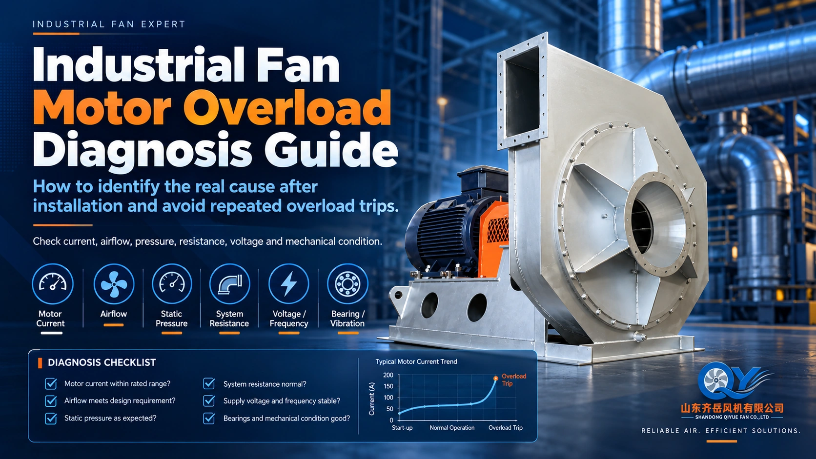
An industrial fan may pass the initial selection review, but after installation the motor can draw higher current than expected, operate close to its rated load or repeatedly trip the overload protection. This does not automatically mean that the motor is too small.
Motor overload can result from the actual operating point, excessive fan speed, gas density, system conditions, electrical supply or mechanical resistance. The fan curve, motor data and real site conditions should therefore be reviewed together before the motor is replaced.
Motor Overload Does Not Automatically Mean the Motor Is Too Small
Motor power should not be evaluated independently from the fan operating point.
A fan performance curve may include airflow, pressure, efficiency, absorbed power and fan speed. The motor is then selected to provide sufficient power for the required duty together with an appropriate engineering margin.
If the installed fan moves away from the original selected operating point, the required shaft power can also change.
For operating-point fundamentals, see How to Read a Fan Performance Curve .
1. The Actual Operating Point May Be Different from the Selected Point
The installed air system determines where the fan actually operates.
Record what differs between the original selection and the operating condition when the overload occurs:
- Reference fan curve, revision and selected operating point.
- Specified gas condition, speed and pressure definition.
- Available airflow and pressure readings, gas temperature and operating state.
- Recorded damper position and filter or process-equipment condition.
- Added or changed ducts, filters, equipment or controls.
- Date of the change and whether the high-current event began before or after it.
When the operating point changes, absorbed power may also change.
The relationship between airflow and absorbed power depends on the fan type, impeller design and actual operating point. Therefore, a universal statement such as “more airflow always causes motor overload” should not be used.
Locate the real operating point on the fan curve and then check the absorbed-power requirement at that point.
If the fan curve appears correct but the measured site airflow is still below the design value, review the installed system before changing fan speed or motor size. See Why Is Fan Airflow Lower Than the Fan Curve After Installation? .
2. Fan Speed May Be Higher Than the Original Selection Basis
Fan speed is one of the first items to check when the motor draws excessive current.
For unchanged fan geometry, approximately unchanged gas density and corresponding points within a stable operating range, airflow scales with fan speed, pressure with speed squared and absorbed shaft power with speed cubed. Review the formulas and their limits in the fan-law guide. These screening relationships do not authorize a speed change or establish motor adequacy.
This means that a relatively small increase in fan speed can produce a much larger increase in absorbed power.
Keep these speed records separate:
- Selected fan RPM and available actual shaft-speed evidence.
- Operating condition and date associated with that evidence.
- Motor nameplate speed and pole data, where available.
- Supply frequency and recorded VFD operating setting, if applicable.
- Direct, belt or coupling arrangement.
- Documented transmission ratio where applicable; mark it unknown if not established.
Do not assume the fan is running at the selected RPM simply because the motor nameplate appears correct.
For RPM, poles and frequency relationships, continue with Motor Poles, RPM, 50 Hz and 60 Hz for Industrial Fans .
3. Gas Density May Be Different from the Design Condition
Gas density affects fan pressure and absorbed power.
For the same fan size, speed and volumetric airflow, a denser gas generally requires more power. This is especially important for boiler fans, furnace exhaust systems and other high-temperature applications.
A fan may be selected for hot process gas with a relatively low density. During cold startup, the same fan can temporarily handle denser air and may require more shaft power.
Does the high-current event occur during cold startup, normal hot operation or another process condition? Record the gas temperature, available current and speed data, and the relevant operating state. Compare that condition with the density basis of the selected curve; the timing alone does not establish the cause.
4. Damper Position and System Resistance Can Change the Motor Load
Damper position changes system resistance and therefore changes the fan operating point.
However, the effect on motor power depends on the fan type and its absorbed-power curve.
“Closing the damper always increases motor load” and “opening the damper always reduces motor load” are not reliable rules for every fan design.
- Document the operating state and available airflow, pressure, gas-condition and actual fan-speed evidence.
- Have the responsible technical team locate that condition on the applicable fan curve and review the absorbed-power requirement.
- Review motor, drive and fan mechanical limits together before agreeing any corrective action.
This is an evidence-review sequence, not an instruction to manipulate a running damper, change speed or bypass protection. Site measurements and inspections require qualified personnel and the applicable safe-work procedures.
5. Confirm the Pressure Basis
Another possible source of error is a mismatch between static pressure and total pressure.
If the project requirement is based on static pressure while the selected fan curve is interpreted using total pressure, or vice versa, the selected operating point may not represent the actual system duty.
This can affect airflow, fan speed, absorbed power and motor sizing.
See Fan Static Pressure vs Total Pressure before comparing site pressure data with the fan curve.
6. Electrical Conditions Should Also Be Verified
Not every high-current condition originates from fan aerodynamics. The site electrical system should also be checked.
Fan-side operating data can help identify whether the required shaft power is reasonable, while site electrical faults should be checked by qualified electrical personnel.
7. Mechanical Drag Can Increase Motor Load
If aerodynamic and electrical conditions appear normal, have the mechanical condition reviewed by qualified personnel. Before intrusive inspection, guard removal or internal access, authorized personnel must apply the site-specific hazardous-energy control procedure, including isolation and verification. Do not reach into the fan or attempt a hand-rotation check while it can start unexpectedly.
Keep shutdown inspection findings separate from operating measurements. Ask the site team to document any rubbing, damaged drive components or bearing concerns, together with the inspection state and corrective-action owner. This article is not a maintenance or lockout procedure. OSHA’s hazardous-energy overview explains unexpected-startup and stored-energy risks; applicable local requirements and the approved site procedure govern the work.
A fan that cannot rotate freely requires additional torque from the motor. Motor current should therefore not be interpreted only as an airflow or system-resistance problem.
8. Do Not Install a Larger Motor Before Finding the Cause
Replacing an overloaded motor with a larger motor can sometimes hide the original problem.
If the real cause is excessive fan speed, an incorrect operating point or mechanical drag, installing a larger motor does not correct the root cause.
Before increasing motor power, confirm the mechanical limits of the fan, including:
- shaft capacity;
- bearing rating;
- impeller strength;
- belt or coupling limits;
- vibration condition;
- maximum safe fan speed.
Practical Troubleshooting Sequence
- Record the motor current, voltage, frequency, fan speed and the operating condition when the overload occurs.
- Compare the measured airflow, pressure and gas condition with the original fan curve and motor selection basis.
- Review damper position, system resistance, drive ratio, electrical supply and any signs of mechanical drag with the site team.
- Identify the cause and confirm the permitted operating range before changing fan speed or motor size.
What Information Should Be Collected?
For a useful fan-side motor overload review, collect as much of the following information as possible.
- Fan and motor nameplate photos, motor rating and the available fan curve.
- Actual current, voltage, frequency, fan RPM, VFD setting and the timing of trips.
- Measured airflow and static or total pressure, gas temperature, medium and damper position.
- Drive, bearing, foundation and duct-connection photos, plus any maintenance or change history.
Continue the Engineering Review
Use the fan curve guide to verify the operating point, the gas-temperature guide for density effects and the installed-airflow guide for system losses.
FAQ: Industrial Fan Motor Overload
Why is my industrial fan motor drawing too much current?
Possible causes include a changed operating point, excessive fan speed, higher gas density, electrical conditions or mechanical resistance. The actual fan curve and site operating data should be checked before concluding that the motor is undersized.
Can higher fan speed overload the motor?
Yes. For the same fan under similar conditions, absorbed power changes approximately with the cube of fan speed, so a relatively small RPM increase can create a much larger increase in required power.
Can cold air cause a high-temperature fan motor to overload?
It can be a factor. Cold air is denser than hot process gas, so some fans selected around a hot-gas operating condition may require more power during cold startup.
Does opening a damper always increase motor current?
Not universally. The result depends on fan type, impeller design and the absorbed-power curve. The new operating point should be checked rather than relying on a general rule.
Should I install a larger motor if the existing motor trips?
Not before identifying the cause. Confirm fan RPM, airflow, pressure, gas condition, electrical supply and mechanical condition first.
Industrial Fan Motor Drawing High Current or Tripping?
Send the available fan curve, motor data and actual operating information. The first step is to determine whether the problem is mainly related to the operating point, fan speed, gas condition, system resistance or mechanical configuration.
Send Your Operating Conditions
Airflow, pressure, gas medium, temperature, voltage and quantity.