01 / Engineering Overview
High Pressure Centrifugal Fan for Heavy Industrial Air Systems
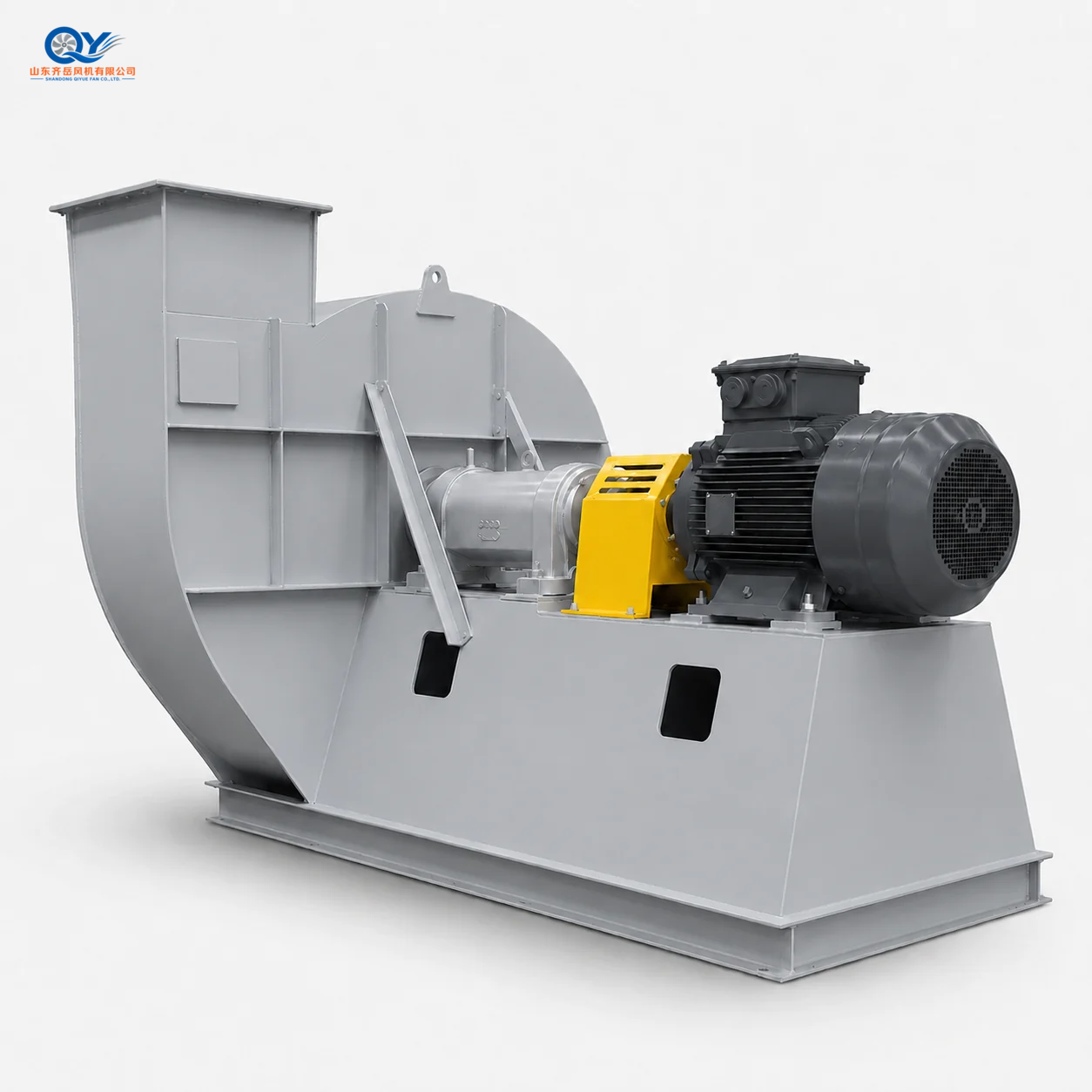
The 10-16 is a high pressure centrifugal fan developed for industrial duties where the required airflow must overcome comparatively high system resistance.
Typical directions include sulfuric acid furnace bottom ventilation after gas-condition confirmation, forging furnace air supply, industrial forced ventilation and selected material-conveying systems.
The documented series uses D-type coupling drive. Final selection should be confirmed from airflow, total pressure, medium condition, temperature, dust content, outlet direction, rotation direction, motor requirement and site layout.
01 / PRESSURE
Pressure-Oriented Duty
Used when ordinary ventilation fans cannot provide the required pressure against connected-system resistance.
02 / DRIVE
D-Type Coupling Drive
Motor power is transmitted through the coupling, shaft and bearing housing to the impeller.
03 / PROJECT
Working-Point Selection
Model number or motor power alone does not confirm whether 10-16 matches the connected system.
02 / Working Condition Boundary
Suitable and Not Recommended Conditions
SUITABLE DIRECTIONS
Review 10-16 When Pressure Matters
Sulfuric acid furnace bottom ventilation or forced air after gas-condition confirmation
Forging furnace air supply and process ventilation
Industrial forced ventilation with relatively high resistance
Material conveying with air or confirmed non-viscous gas
High-resistance duct and process-air systems
Heavy-duty projects requiring D-type coupling drive
NOT FIRST CHOICE
Check Another Fan or Special Design
General low-pressure workshop ventilation
Strong corrosive gas without anti-corrosion design
High-temperature gas above the standard design range
Sticky dust or wet-dust conveying
Explosion-proof areas without confirmed configuration
Very high particle concentration without wear-resistant evaluation
03 / Product Position
Why 10-16 Is Used in High-Resistance Systems
10-16 belongs to the high-pressure centrifugal fan family rather than general low-pressure ventilation equipment. Its selection direction is defined by system resistance and the required operating point.
01 / RESISTANCE
High System Loss
Ducts, dampers and process equipment can require substantially more pressure than ordinary ventilation systems.
02 / FURNACE
Furnace Air Supply
Pressure-oriented airflow supports furnace and process-air applications where stable forced air is required.
03 / DRIVE
Coupling Transmission
The D-type arrangement separates the motor and impeller shaft through coupling and bearing housing.
04 / SELECTION
Pressure Is Not Enough
Airflow and pressure must be checked together at the same working point before the fan and motor are confirmed.
04 / High Pressure Family
Where 10-16 Fits Among High Pressure Fan Series
Compare the actual airflow, total pressure, pressure-loss source, drive arrangement and medium condition before deciding whether 10-16 or another high-pressure series is the better starting point.
SERIES
POSITION
WHEN TO COMPARE
10-16
Heavy-duty high pressure
Specified 10-16 duty or D-type coupling working point requiring dedicated verification.
9-19
Pressure-first forced air
Pressure-oriented forced-air duties where airflow, motor range and arrangement require comparison.
9-26
Higher airflow + pressure
Larger airflow combined with high resistance in heavy industrial, conveying or process-air systems.
9-12
High-resistance process air
Pressure demand driven mainly by long ducts, elbows, dampers or process equipment resistance.
06 / Typical Model Reference
10-16 Model Range for Preliminary Screening
Use the following rows for initial series screening only. Final performance, motor, outlet angle, rotation and installation dimensions should be confirmed before production.
MODEL
SPEED
AIRFLOW
PRESSURE
POWER
10-16 No.6.8
2960
3,180–4,200
11,400–16,000 Pa
30–45 kW
10-16 No.7.1
2960
4,200–5,600
12,000–16,500 Pa
45–55 kW
10-16 No.7.4
2960
5,600–8,000
12,800–17,000 Pa
55–75 kW
10-16 No.8.1
2960
8,000–12,050
13,000–17,230 Pa
75–90 kW
Airflow values are in m³/h and speed values are in r/min. These rows are preliminary reference data only.
07 / Structure & Components
Heavy-Duty D-Type Centrifugal Fan Structure
Impeller
Generates the airflow and pressure required by the connected system.
Volute Casing
Collects airflow leaving the impeller and directs it toward the discharge outlet.
Air Inlet
Guides incoming air into the impeller inlet.
Bearing Housing & Coupling
Supports shaft operation and transfers motor power through the coupling.
Motor & Integral Base
Provides driving power and a stable installation platform for the complete assembly.
08 / Outlet Direction & Installation
Confirm Direction and Interface Before Production
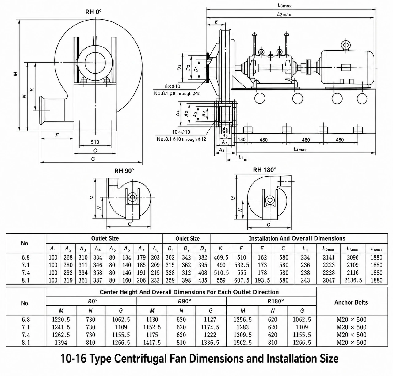
The documented 10-16 configuration includes RH 0°, RH 90° and RH 180° outlet directions. Rotation, outlet position and installation dimensions should be checked against the project layout before production.
Outlet Direction
RH 0°, RH 90° and RH 180° are listed in the current product reference.
Rotation
Right-hand or left-hand rotation should be confirmed against the actual duct arrangement.
Foundation
Confirm base dimensions, anchor bolts, shaft-center height and available installation space.
Maintenance Space
Leave sufficient space for motor installation, coupling maintenance, bearing inspection and duct connection.
Replacement projects: send the existing fan drawing, foundation dimensions, inlet and outlet dimensions, rotation, outlet angle and available equipment space before dimensional confirmation.
Typical Applications
High Pressure Industrial Airflow Applications
01 / FURNACE
Sulfuric Acid Furnace
Bottom ventilation or forced-air supply after medium and corrosion conditions are confirmed.
02 / FORGING
Forging Furnace Air
High-pressure process-air supply for forging furnace and heating systems.
03 / FORCED AIR
Industrial Forced Ventilation
Forced-air systems where relatively high resistance must be overcome.
04 / CONVEYING
Material Conveying
Selected process-air and pneumatic-conveying duty after medium and resistance review.
05 / METALLURGY
Metallurgical Process Air
Heavy industrial airflow systems requiring pressure-oriented fan selection.
06 / DUCT
High-Resistance Ducts
Systems where long ductwork or connected equipment creates substantial pressure loss.
09 / Selection Logic
What to Send for 10-16 Fan Selection
Do not select a 10-16 fan only from motor power, fan size or inlet diameter. Start from the actual operating point and installation conditions.
01
Required Airflow
Determines the basic fan size and operating point.
02
Total Pressure
Confirms whether the 10-16 pressure region matches the system.
03
Medium
Provide gas composition and any corrosion, combustion or safety conditions.
04
Temperature
Confirm normal and maximum gas temperature.
05
Dust Content
Dust concentration affects wear evaluation and maintenance planning.
06
Outlet / Rotation
Confirm outlet position and rotation according to the duct layout.
07
Power Supply
Provide voltage, frequency and phase for motor configuration.
08
Installation Layout
Send foundation, duct connection, available space and quantity.
Related Selection Paths
Continue from the Fan to the System
10 / Buyer FAQ
10-16 High Pressure Centrifugal Fan Questions
What is the 10-16 high pressure centrifugal fan used for?
It is used for sulfuric acid furnace bottom ventilation after working-condition confirmation, forging furnace air supply, industrial forced ventilation and selected material-conveying systems where higher pressure is required.
Is 10-16 suitable for general workshop ventilation?
It should normally be reviewed when the system requires higher pressure. For ordinary low-resistance workshop ventilation, a lower-pressure centrifugal or axial fan may be more appropriate.
What medium can the standard 10-16 reference handle?
The documented reference condition is air or non-corrosive, non-spontaneous-combustion and non-viscous gas. Corrosive, high-temperature, explosive or heavy-dust service requires separate evaluation.
What temperature and dust limits are listed?
The current product reference lists medium temperature normally at or below 80°C and dust content normally at or below 150 mg/m³.
Can the outlet direction be changed?
The documented reference lists RH 0°, RH 90° and RH 180°. Rotation and outlet direction should be confirmed according to the site duct layout before production.
How should 10-16 be compared with 9-19 and 9-26?
Compare actual airflow, total pressure, resistance source, drive arrangement, medium condition and installation layout. The model name alone does not replace working-point verification.
What information is required for quotation?
Provide airflow, total pressure, medium composition, temperature, dust content, voltage, frequency, outlet direction, rotation direction, installation layout and quantity.