
Centrifugal Fan Drive Arrangements Explained: A, B, C, D, E and F Types
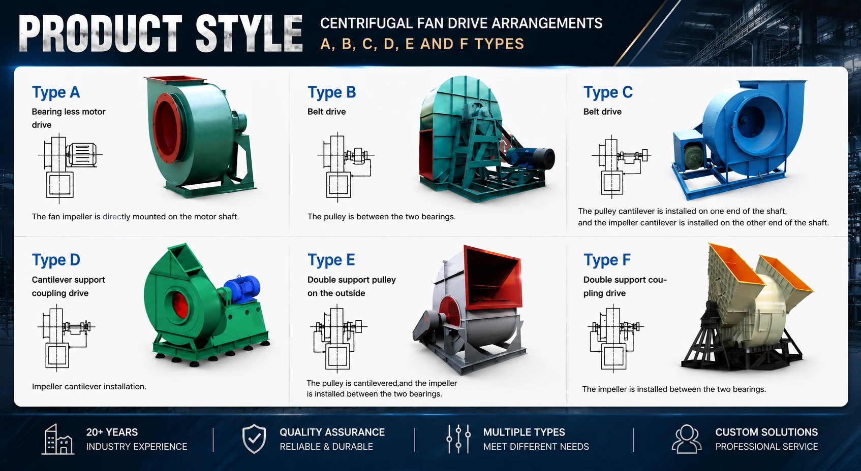
Drive arrangement defines how the motor, impeller, shaft, bearings and transmission are assembled. This guide focuses specifically on A–F centrifugal fan drive and support types commonly used in manufacturer and fan-series terminology.
The two systems describe related mechanical features but should not be converted directly. Always confirm the approved fan drawing before production.
What Does Centrifugal Fan Drive Arrangement Mean?
In a centrifugal fan, the drive arrangement describes how the motor drives the impeller and how the shaft, bearings, pulleys or coupling are positioned. Two fans may have similar airflow and pressure but require different mechanical structures because of speed, temperature, dust loading, motor power, foundation and maintenance conditions.
For example, a model such as 4-72 No.10D may use a letter to indicate a drive form. The exact meaning of an A–F code should always be checked against the applicable fan series and approved general arrangement drawing.
Belt ratios can adjust fan speed, while direct and coupling layouts are more closely related to motor and fan shaft speed.
Different shaft and bearing support layouts create different vibration, loading and foundation requirements.
Belts, bearings, couplings and motors require different inspection, adjustment and removal space.
Motor position, duct direction, outlet angle and base dimensions must fit the installation site.
Quick Comparison of A, B, C, D, E and F Types
In this guide, A–F are used as manufacturer or fan-series terminology for mechanical drive and support features, not airflow direction. They should not be treated as universal numbered arrangement codes. Exact meanings can vary between fan series, so the following descriptions are practical selection references rather than a substitute for an approved drawing.
| Type | Common description | Typical structural feature | Confirm before ordering |
|---|---|---|---|
| A | Direct drive | Impeller mounted directly on the motor shaft. | Motor frame, speed, shaft, temperature and service access. |
| B | Belt drive with cantilever or overhung support | A separate motor drives the fan shaft through belts and pulleys; shaft and bearing layout is fan-series specific. | Pulley position, belt guard, bearing support, shaft load and maintenance side. |
| C | Common belt-drive form | The motor drives the fan shaft through a belt-and-pulley set, with the exact shaft extension and bearing layout defined by the fan series. | Fan speed, pulley ratio, shaft extension, bearing seats, guard and service space. |
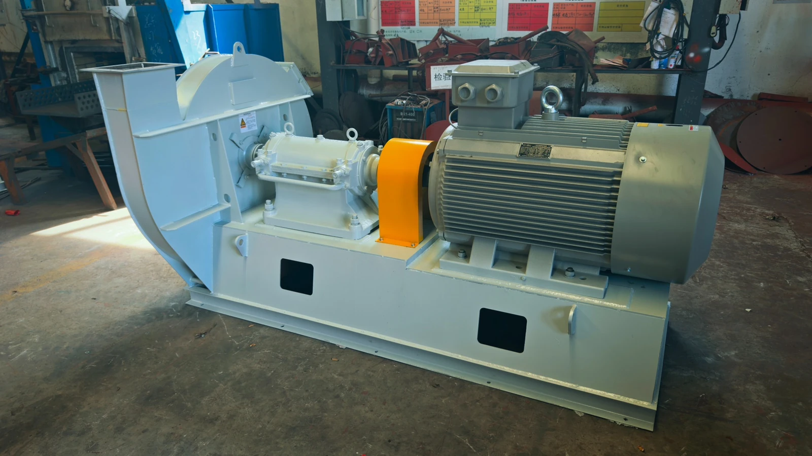
| D | Coupling drive | Motor and fan shaft connected through a coupling. | Coupling type, alignment, base, guard and foundation clearance. |
| E | Double-support belt drive | The fan shaft or impeller is supported by bearings on both sides while the motor drives the shaft through belts and pulleys; exact pulley position is fan-series specific. | Bearing span, shaft load, pulley position, belt guard and service space. |
| F | Double-support coupling drive | A heavier-duty shaft and bearing arrangement commonly used for larger industrial fans. | Bearing span, shaft loads, foundation, coupling alignment and installation space. |
Looking for Numbered Centrifugal Fan Arrangements?
Numbered arrangements such as Arrangement 1, 3, 4, 7, 8, 9 and 10 describe the mechanical relationship between the wheel, shaft, bearings, motor and drive system. They use a different classification approach from the A–F drive codes explained on this page.
For detailed bearing layouts, wheel positions, SWSI/DWDI configurations and arrangement-by-arrangement comparisons, use the dedicated numbered arrangement guide.
What to Confirm Before Selecting a Drive Arrangement
There is no single best drive arrangement for every centrifugal fan. The correct choice depends on the duty point, fan size, operating speed, motor power, working medium, temperature, dust loading and installation conditions.
Use the Industrial Fan Selection Guide together with the fan series, performance curve and approved drawing.
Information Required for Drive Arrangement Confirmation
For quotation, replacement or drawing approval, provide as much of the following information as possible:
Airflow, static or total pressure, fan speed and operating point.
Power, voltage, frequency, speed, frame size and starting method.
Temperature, dust loading, moisture, corrosive components and density.
Drive type, shaft, bearing position, motor position and foundation.
Rotation direction, viewing side, inlet, outlet angle and duct direction.
Old model, nameplate photo, side-view photo, drawing and existing base dimensions.
Continue with Fan Selection and Product Information
Frequently Asked Questions About A–F Centrifugal Fan Drive Arrangements
What do A–F codes mean in a centrifugal fan?
A–F codes describe manufacturer or fan-series drive and support arrangements involving the motor, impeller, fan shaft, bearings, belt drive or coupling. Exact definitions should be checked against the applicable fan model and approved drawing.
Are A–F codes the same as Arrangement 1, 3, 4, 7, 8, 9 and 10?
No. They are related mechanical-layout terminology but should not be converted directly from one system to the other. A–F meanings can depend on the fan series or manufacturer. For numbered mechanical layouts, see the Centrifugal Fan Arrangement Types Guide .
What does A mean in an A–F centrifugal fan drive arrangement?
A commonly refers to a direct-drive layout with the impeller mounted directly on the motor shaft. Motor frame, fan speed, shaft compatibility, operating temperature and service access must be confirmed for the selected fan series.
What is the difference between B, C and E?
B and C are commonly used for belt-drive forms whose exact shaft and bearing layouts depend on the fan series. E generally indicates a double-support belt-drive form. Pulley position, belt guard, bearing seats, shaft load and maintenance clearance should be confirmed from the approved drawing.
What is the difference between D and F?
D commonly refers to a coupling-drive layout. F generally refers to a double-support coupling-drive form. Coupling type, bearing span, alignment, foundation and service space must be confirmed for the actual fan series.
Can a centrifugal fan drive arrangement be selected from airflow and pressure only?
No. Airflow and pressure define the aerodynamic duty, but drive arrangement selection also requires fan speed, motor power, working temperature, gas condition, shaft and bearing layout, rotation, outlet angle, foundation, maintenance space and fan series.
Need Help Confirming a Centrifugal Fan Drive Arrangement?
Send the airflow, pressure, speed, motor data, working temperature, gas condition, installation direction, existing fan drawing or nameplate photo. QIYUE FAN can review the suitable drive, bearing and mechanical configuration for your project.
QIYUE FAN | Industrial Fan Manufacturer | +86 15653305981 | sales@qiyuefan.com
Send Your Operating Conditions
Airflow, pressure, gas medium, temperature, voltage and quantity.