
An underground mine ventilation system supplies fresh air to active workings, controls the return-air route and supports heading-face ventilation through a coordinated combination of main fans, auxiliary fans, local fans, ducts and airflow-control structures.
Fan selection must be based on the complete underground airflow network, including required airflow, pressure resistance, roadway development, ventilation distance, duct condition, mine type, installation method, electrical standard and project safety requirements.
What an Underground Mine Ventilation System Must Do
The ventilation network must continuously deliver useful fresh-air volume to underground roadways and active working zones while directing contaminated return air toward the designated exhaust route.
The operating point changes as the mine develops. Roadway length, new branches, regulators, duct extension, leakage and changing working zones all influence airflow and pressure demand.
Main Ventilation and Local Ventilation Work Together
A complete mine ventilation system normally combines a primary airflow network with local ventilation equipment serving development headings and isolated working zones.
Main Mine Ventilation
Main fans establish the overall fresh-air and return-air route. Selection is based on total network airflow, system resistance, mine development and operating strategy.
Local and Auxiliary Ventilation
Local fans supply or extract air through flexible or rigid ducting where the primary airflow does not directly reach the active heading.
Different Underground Mines Require Different Ventilation Strategies
The fan family, installation arrangement and safety configuration depend on the mine environment. Coal-mine duty should not be treated as identical to metal or non-coal underground ventilation.
Coal Mine Ventilation Network
Main and local airflow arrangements must be reviewed together with mine gas, dust, installation conditions and project-specific safety requirements.
Metal and Non-Coal Mines
Ventilation is matched to mine depth, roadway resistance, blasting fumes, dust conditions, equipment zones and the distribution of active underground workings.
Changing Underground Work Areas
As headings advance and branches are added, ventilation distance and resistance change. Fan duty should be reviewed against both current and planned mine development.
Why Ventilation Distance and Duct Condition Matter
A local ventilation fan must operate at the airflow-pressure point required by the complete duct system. Duct friction and fittings increase the pressure required to move air, while leakage changes how much useful airflow is actually delivered to or captured from the working face.
A larger fan does not automatically solve low airflow. Excessive resistance can shift the fan operating point to a lower flow, while duct leakage, poor joints, short-circuiting or recirculation can reduce useful face airflow even when total fan airflow appears high.
Air Quantity and Velocity
Q = airflow, m³/s; A = effective airway or duct cross-sectional area, m²; v = average air velocity, m/s.
System Resistance and Pressure
For the same system resistance and comparable air-density condition, required pressure varies approximately with the square of airflow. The actual project calculation must use the real airway or duct network and operating condition.
How Airflow Is Distributed Through the Mine Network
Mine ventilation is a network problem. Fan airflow must be distributed through intake and return routes, branches, regulators, doors, leakage paths and local duct systems. A high total fan airflow does not guarantee that every active workplace receives the required fresh-air quantity.
Resistance Adds Along the Route
Airways or duct sections in series carry the same airflow one after another. Their pressure losses accumulate, so additional length, bends, restrictions or damaged sections increase the total pressure required for the selected airflow.
Airflow Divides Between Branches
Parallel branches share airflow according to their resistance and connected pressure conditions. A restricted branch can receive less air while a lower-resistance path receives more, so regulators and airway changes should be reviewed against the whole network.
Check Where the Air Actually Goes
For branches compared at compatible air-density conditions, a large unexplained imbalance can indicate leakage, an open control, an unrecorded connection, a poor measurement station or readings taken under different operating conditions.
Press-In, Extractive and Combined Ventilation
The appropriate arrangement depends on heading-face conditions, contaminant-control objectives, fan position, duct layout and the complete underground airflow route.
Press-In Ventilation
Fresh air is supplied through ventilation ducting toward the heading face. Fan pressure must overcome the resistance of the complete duct route. Leakage should be considered separately because it reduces useful airflow delivered at the duct outlet.
Extractive Ventilation
Contaminated air is drawn from the working area into the duct. Fan location, dust condition, gas characteristics, duct airtightness and the return-air route should be reviewed.
Combined Ventilation
Supply and exhaust equipment are coordinated where the project requires more controlled heading-face airflow or contaminant removal. Fan duties and duct positions must be reviewed as one local ventilation system.
Low Face Airflow Does Not Always Mean the Fan Is Too Small
Before increasing fan power or replacing a local fan, confirm whether the shortfall comes from fan duty, duct resistance, leakage or airflow routing. The same symptom can be produced by very different system problems.
Excessive Resistance
Long duct runs, small diameter, bends, reducers, blocked screens, collapsed ducting or restricted roadways can move the operating point to lower airflow and higher pressure.
Duct Leakage
In forcing systems, leakage reduces the quantity reaching the duct outlet. In exhausting systems, leaks can draw roadway air into the duct so fan flow exceeds useful capture at the working face.
Short-Circuiting
Air can take an unintended low-resistance path from intake to return without ventilating the target area. Open doors, damaged stoppings, incorrect regulator settings or new connections can create this condition.
Recirculation
Contaminated return air can be drawn back toward an intake or local fan when intake and discharge paths are poorly separated. Total fan airflow may appear adequate while fresh-air delivery remains insufficient.
Parameters Required for Underground Mine Ventilation Fan Selection
Complete project information helps determine whether the mine requires a main fan, auxiliary fan, local duct fan, counter-rotating fan or another ventilation arrangement.
What Should Be Measured Before Changing Fan Duty?
A calculation or ventilation model should be checked against actual field conditions before a major fan-duty change is confirmed. Record the measurement location, fan operating condition and pressure definition so values can be compared on the same basis.
Airflow Measurements
Pressure & Fan Condition
Project Conditions
Typical Fan Families Used in Underground Mine Ventilation
Choose the fan direction from the actual ventilation duty. Local press-in and extractive systems should be separated from mine-wide main or auxiliary ventilation when reviewing candidate fan families.
FBD Local Ventilation Fan
Press-in duct ventilation direction for underground headings and local working areas.
FBCD Extractive Local Ventilation Fan
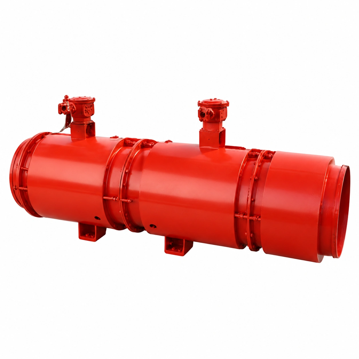
Explosion-proof counter-rotating fan for negative-pressure duct extraction in underground coal-mine roadways and headings.
FBCDZ Mine Main Ventilation Fan
Counter-rotating main ventilation direction for coal-mine airflow networks.
K / DK Mine Ventilation Fan
Main or auxiliary ventilation direction for underground airflow networks.
FKZ / FKCDZ Mine Fan
Main and auxiliary ventilation for metal and non-coal underground mines.
New Mine Ventilation Projects and Existing Fan Replacement
Build the Fan Duty from the Ventilation Network
For a new underground project, selection should begin with planned airflow distribution and system resistance rather than a preselected fan model.
Do Not Replace an Existing Fan by Model Name Alone
Existing fan performance, installation interfaces and actual duct or roadway conditions should be checked before confirming a replacement direction.
From Mine Data to Fan Selection
Engineering References and Fan-Selection Basis
This page connects mine ventilation-system duty with industrial fan selection. Final mine-wide ventilation design, legal compliance and statutory approval remain the responsibility of the mine’s qualified ventilation personnel or appointed engineering consultant.
Fan selection should connect required airflow and pressure with the complete system resistance, actual installation condition, fan performance curve, motor specification and project documentation.
Selected Engineering References
Continue the Mine Ventilation Engineering Review
Mine Ventilation Fan Families


Send Your Operating Conditions
Airflow, pressure, gas medium, temperature, voltage and quantity.