
Centrifugal Fan Arrangement Types Explained: Arrangement 1, 3, 4, 7, 8, 9 And 10
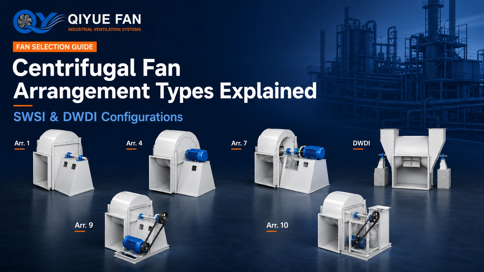
A centrifugal fan arrangement identifies how the impeller, shaft, bearings, motor and drive system are mechanically positioned. The arrangement affects installation space, bearing support, motor location, transmission method, maintenance access and foundation design.
What Does a Centrifugal Fan Arrangement Number Mean?
A centrifugal fan arrangement number describes the physical relationship between the impeller, fan shaft, bearings, motor and drive components. If you are new to centrifugal fan structure and airflow principles, start with What Is a Centrifugal Fan? before comparing arrangement numbers. It helps engineers understand whether the wheel is overhung or positioned between bearings, whether the motor is mounted separately or on the fan structure, and whether power is transmitted through belts, a coupling or directly through the motor shaft.
Two centrifugal fans can produce similar airflow and pressure while using very different arrangements. The final arrangement should therefore be confirmed together with fan size, speed, motor power, process temperature, shaft loading, foundation and maintenance requirements.
Arrangement Numbers vs A–F Drive Types
Numbered fan arrangements describe the complete mechanical layout, especially the relationship between the wheel, shaft, bearings and motor. A–F codes commonly used with Chinese centrifugal fan series describe another drive and support naming system.
They are related concepts, but there is no universal one-to-one conversion between an A–F code and Arrangement 1, 3, 4, 7, 8, 9 or 10.
SWSI and DWDI Centrifugal Fan Arrangements
Single Width, Single Inlet
An SWSI centrifugal fan uses one inlet and a single-width impeller. Common numbered arrangements include Arrangement 1, 3, 4, 7, 8, 9 and 10, together with application-specific variants.
Double Width, Double Inlet
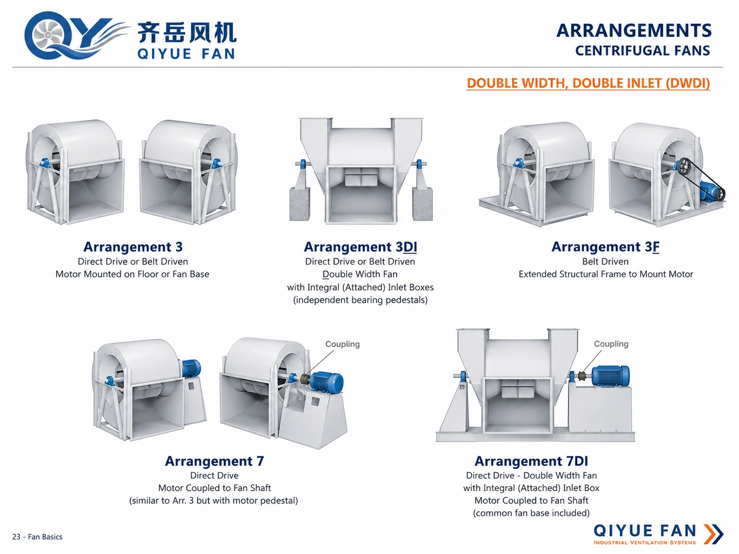
A DWDI centrifugal fan uses a wider double-inlet impeller with airflow entering from both sides. The shaft, two inlet structures, bearing locations and motor arrangement must be coordinated with the larger double-width assembly.
Common Centrifugal Fan Arrangement Groups
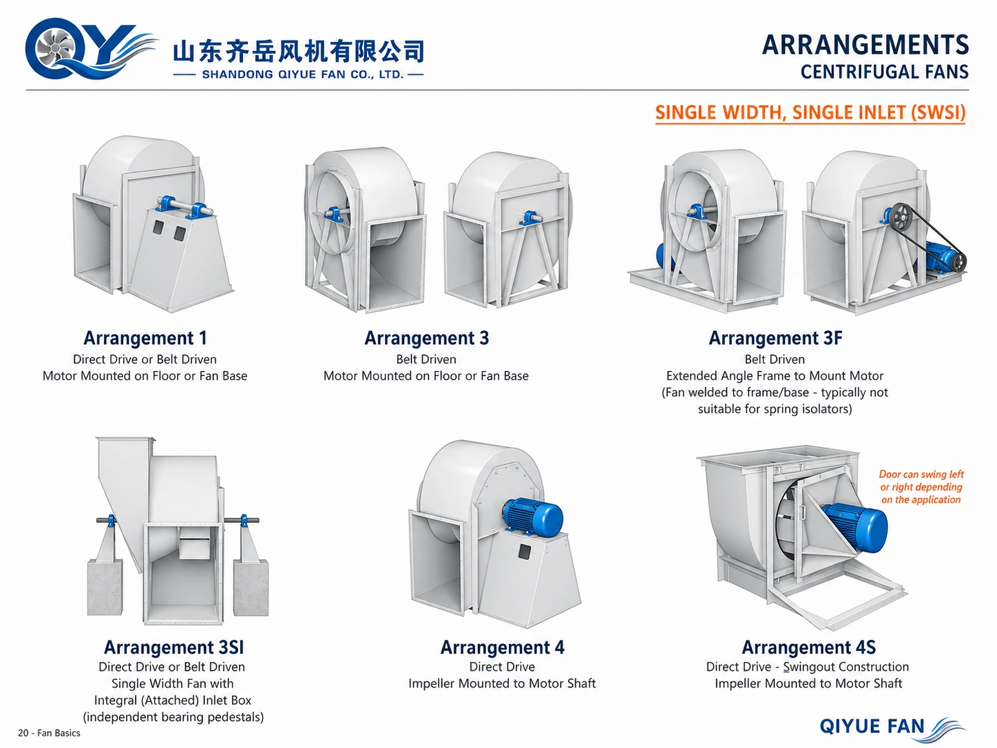
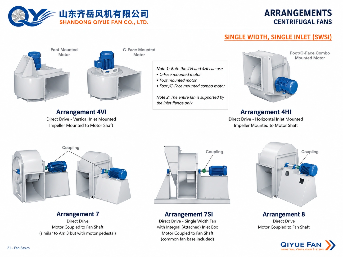
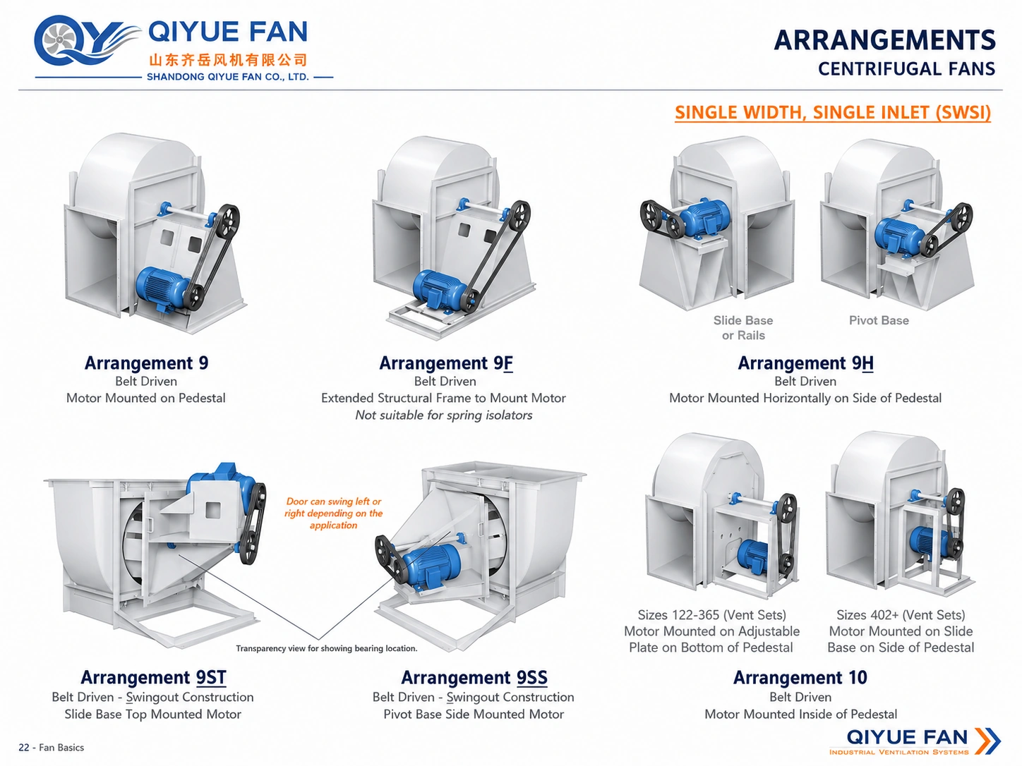
These diagrams are useful for identifying common mechanical layouts. They are reference illustrations only; final bearing positions, motor location, dimensions, rotation and discharge direction should be confirmed on the approved general arrangement drawing.
Arrangements 1, 3, 3F, 3SI, 4 and 4S
The SWSI reference diagrams lower on this page show the relative wheel, shaft, bearing and drive positions for this group. Use them for orientation and confirm the selected arrangement on an approved GA drawing.
Direct-Drive and Coupling-Connected Variants
The drive connection changes the motor position and maintenance envelope. Compare the arrangement reference with the selected drive type; verify dimensions and coupling details for the actual project.
Arrangements 9, 9F, 9H, 9ST, 9SS and 10
These labels represent related layouts with different motor or bearing positions. The reference drawing below is a visual guide; the project GA drawing controls the final configuration.
DWDI Arrangements 3, 3DI, 3F, 7 and 7DI
For double-inlet fans, confirm the wheel, two inlet connections, shaft, bearings and drive position against the actual equipment drawing before a replacement decision.
Arrangement 1, 3, 4, 7, 8, 9 and 10 Explained
The following sections focus on the mechanical distinctions most useful for fan selection, replacement projects and bearing-layout identification.
Arrangement 1 Fan – Overhung Wheel with Independent Bearings
In a typical Arrangement 1 SWSI fan, the impeller is overhung on a separate fan shaft. Two fan bearings support the shaft on a pedestal or bearing base. The motor is separate from the impeller shaft and the fan may use belt drive or another suitable shaft-drive configuration depending on the design.
The key identifying feature is the overhung wheel with a separately supported fan shaft. Bearing spacing, shaft diameter, pulley position and motor location must be checked on the drawing.
Arrangement 3 Fan Bearing Configuration – Wheel Between Bearings
The defining feature of an Arrangement 3 fan bearing configuration is that the impeller is mounted on a fan shaft between two bearings. The bearings may be supported by the fan casing or mounted on independent bearing pedestals, depending on the fan construction.
This between-bearing layout gives a different shaft-support condition from an Arrangement 1 overhung fan. Arrangement 3 can be used with belt or shaft-connected drive configurations according to the specific fan design.
Arrangement 4 Fan – Impeller Mounted on Motor Shaft
Arrangement 4 is a direct-drive centrifugal fan layout. The impeller is overhung directly on the motor shaft, so there is no separate fan shaft or external fan bearing set. The compact structure reduces transmission components, but motor speed, motor bearing load, operating temperature and access for motor removal must be reviewed carefully.
Arrangement 7 Fan – Between-Bearing Shaft with Coupling Drive
Arrangement 7 is generally based on an Arrangement 3-style between-bearing fan shaft, but the motor or prime mover is connected to the fan shaft through a coupling. Coupling alignment, bearing centerline, common-base rigidity and motor-removal clearance are therefore important parts of the installation design.
Arrangement 8 Fan Bearing Configuration – Overhung Wheel with Inline Motor
Arrangement 8 generally retains the overhung wheel and independent fan-bearing structure associated with Arrangement 1, while the motor is installed in line with the fan shaft on the fan base or support structure.
In an Arrangement 8 fan bearing layout, the fan shaft remains independently supported rather than placing the impeller directly on the motor shaft. Final coupling, bearing and pedestal geometry should be confirmed on the manufacturer’s drawing.
Arrangement 9 Fan Bearing and Motor Layout
Arrangement 9 is a belt-driven configuration with an overhung impeller on a separately supported fan shaft. Two bearings are mounted on the bearing pedestal or fan base, while the motor is mounted outside the bearing pedestal structure.
Depending on the specific Arrangement 9 variant, the motor may be installed on the pedestal, an extended frame, the side of the pedestal or a swingout structure.
Arrangement 10 Fan Bearing and Belt-Drive Layout
Arrangement 10 is also a belt-driven overhung-wheel arrangement with an independent fan shaft and two fan bearings. The principal motor-position difference from Arrangement 9 is that the motor is installed inside the bearing pedestal or support structure.
The compact external footprint can be useful where installation space is limited, but motor cooling, inspection access, belt replacement and motor-removal clearance must be checked before finalizing the layout.
Arrangement 1 vs Arrangement 3 Fan Bearings
The impeller is located outside the two-bearing span. The shaft is supported by two bearings on one side of the wheel.
The impeller is positioned within the bearing span, with one bearing supporting the shaft on each side of the wheel.
Common SWSI and DWDI Arrangement Variants
Industrial fan manufacturers may use additional suffixes to identify motor frames, inlet boxes, swingout structures and double-inlet configurations. The exact designation should always be checked against the supplier drawing.
Centrifugal Fan Arrangement Comparison
| Arrangement | Wheel / Bearing Layout | Typical Drive | Motor Relationship |
|---|---|---|---|
| 1 | Overhung wheel, separate fan shaft, two bearings | Belt or shaft-connected | Motor separate from wheel shaft |
| 3 | Wheel positioned between two bearings | Belt or shaft-connected | Independent fan shaft |
| 4 | No separate fan bearings | Direct drive | Wheel mounted directly on motor shaft |
| 7 | Wheel between bearings | Coupling drive | Motor coupled to fan shaft |
| 8 | Overhung wheel with independent fan bearings | Inline direct / coupling connection | Motor inline with fan shaft |
| 9 | Overhung wheel, two fan bearings | Belt drive | Motor outside bearing pedestal |
| 10 | Overhung wheel, two fan bearings | Belt drive | Motor inside bearing pedestal |
Configuration descriptions are general engineering references. Manufacturer-specific variants and dimensional details must be confirmed on the final general arrangement drawing.
How to Select the Correct Fan Arrangement
Arrangement should be selected after the aerodynamic duty is known, but airflow and pressure are only the starting point. Mechanical and installation conditions are equally important.
- Overall footprint, duct direction, motor clearance and maintenance aisle.
- Direct, belt or coupling connection; identify any speed-adjustment requirement.
- Wheel position, actual fan speed, shaft length and transmitted load.
- Review whether the motor and bearings need separation from hot gas.
- Bearing inspection, belt replacement, coupling alignment and motor removal.
- Common base, concrete foundation and any specified vibration-isolation arrangement.
Information Required for Arrangement Selection
For a new fan or replacement project, send the technical data and installation information together. Existing fan drawings and nameplate photos are especially useful for replacement applications.
- Required airflow and static or total pressure
- Actual fan shaft speed; motor speed separately if known
- Operating temperature
- Gas composition and dust concentration
- Motor power, voltage and frequency
- Preferred drive method
- Available installation space
- Inlet and outlet duct direction
- Foundation or vibration-isolation requirements
- Existing fan model or nameplate
- General arrangement drawing, if available
If only motor speed is known, identify the drive arrangement and any transmission ratio before treating it as fan shaft speed. The final arrangement and dimensions remain subject to the approved equipment drawing.
Frequently Asked Questions About Fan Arrangements
What is an Arrangement 3 fan bearing configuration?
In an Arrangement 3 fan bearing configuration, the impeller is mounted on the fan shaft between two bearings. This is the main mechanical distinction from an Arrangement 1 fan, where the impeller is overhung outside the bearing span.
Where are the bearings located in Arrangement 8?
An Arrangement 8 fan generally uses an independently supported fan shaft with an overhung wheel. The motor is positioned inline with the fan shaft. Exact Arrangement 8 fan bearing positions and coupling geometry should be confirmed from the manufacturer’s drawing.
What is the difference between Arrangement 1 and Arrangement 3?
Arrangement 1 uses an overhung wheel on a shaft supported by two bearings located on one side of the impeller. Arrangement 3 positions the wheel between two bearings.
What is the difference between Arrangement 4 and Arrangement 7?
Arrangement 4 mounts the impeller directly on the motor shaft and does not use separate fan bearings. Arrangement 7 uses a separately supported fan shaft with the motor connected through a coupling.
What is an Arrangement 9 fan bearing layout?
Arrangement 9 uses an overhung impeller, a separate fan shaft and two fan bearings on the bearing pedestal. It is normally belt driven, with the motor mounted outside the bearing pedestal structure.
What is an Arrangement 10 fan bearing configuration?
Arrangement 10 also uses an overhung wheel, separate fan shaft and two fan bearings. It is belt driven, with the motor installed inside the bearing pedestal or supporting structure.
What is the difference between Arrangement 9 and Arrangement 10?
Both are commonly belt-driven overhung-wheel configurations. Arrangement 9 places the motor outside the bearing pedestal, while Arrangement 10 places the motor inside the pedestal structure.
Are arrangement numbers the same as A, B, C, D, E and F drive types?
No. Both describe mechanical aspects of centrifugal fans, but they belong to different naming systems. Do not directly convert an A–F code into Arrangement 1, 3, 4, 7, 8, 9 or 10 without checking the actual fan drawing.
What is the difference between SWSI and DWDI?
SWSI means single width, single inlet. DWDI means double width, double inlet. DWDI fans admit air from both sides of the impeller and require a wider shaft and bearing arrangement.
Can a fan arrangement be selected from airflow and pressure only?
No. Airflow and pressure determine the aerodynamic operating duty. Arrangement selection must also consider fan speed, shaft and bearing loads, motor power, temperature, drive method, installation space, foundation and maintenance access.
Continue Your Centrifugal Fan Selection
Compare the mechanical layout with the A–F drive arrangements guide and confirm rotation and outlet position using the rotation and outlet angle guide. Then review the operating duty in the fan selection process.
Need Help Confirming a Centrifugal Fan Arrangement?
Send the required airflow, pressure, fan speed, motor data, operating temperature, installation space, existing fan drawing or nameplate photo. QIYUE FAN can review the suitable bearing, shaft, drive and motor arrangement for your project.
Original Fan Arrangement Reference Diagrams
The four reference drawings retain their original labels and layouts. Source-specific size labels, suffixes and mounting notes are reference examples, not QIYUE availability or installation specifications; the approved project GA drawing governs. Spring-isolator suitability is construction-specific; do not use these reference-image notes as installation instructions.
Send Your Operating Conditions
Airflow, pressure, gas medium, temperature, voltage and quantity.