
Industrial Fan General Arrangement Drawing Guide
A Fan Can Meet the Duty Point and Still Fail at Installation
Selecting the correct airflow and pressure does not guarantee that an industrial fan will fit the project. A fan may be aerodynamically correct but still create major site problems if the installation interfaces are wrong.
Typical causes include an inlet centerline that does not match the duct, the wrong outlet direction, foundation holes that do not align, interference from the motor or belt guard, or insufficient space for future maintenance.
These problems often become expensive only after the fan arrives at site. Correction may require duct modification, foundation rework, support-frame modification, transition pieces, extra shutdown time or delayed commissioning.
Can the Fan Do the Job?
Verify the required airflow, pressure, medium, temperature and motor duty against the proposed fan curve.
Can the Fan Fit the Job?
Check the GA drawing against the actual duct, foundation, discharge orientation, motor envelope and maintenance clearance before approval.
The Five Interfaces Most Likely to Cause Site Rework
Most installation problems are not caused by the fan casing itself. They are caused by the points where the fan must connect to the duct, foundation, available space and maintenance environment.
Duct Interface
Matching the nominal opening size is not enough. The connection position must also match. A correct inlet diameter can still require site modification if the centerline or flange position is wrong.
If the interface includes a flexible connection, use the flexible connector RFQ checklist to confirm mating details, duty suitability and which accessories are included or supplied by others.
Foundation Interface
Two fans can have similar overall dimensions and completely different mounting-hole layouts. Similar fan size does not guarantee that the new fan can sit on the existing support.
Installation Envelope
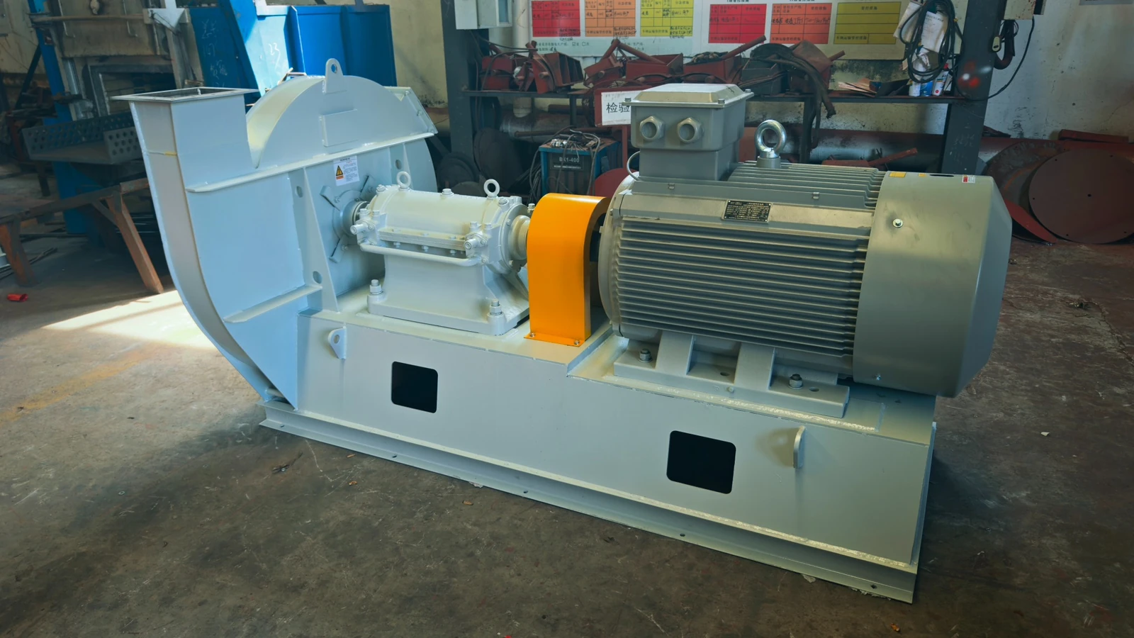
The casing may fit while the motor, belt guard, coupling or bearing section conflicts with walls, structures, pipework or platforms.
Mechanical Configuration
The same fan family can be supplied in different physical arrangements. Rotation, outlet direction and drive position can determine whether the fan connects correctly.
Maintenance Interface
Installation clearance gets the fan into position. Maintenance clearance keeps the fan serviceable for years.
Before approving the layout, review the delivery route, shipping envelope and service-space checklist with the site team. Installed footprint alone does not establish access for delivery or future component removal.
From Engineering Drawing to Installation Decision
Apply the checks below to the proposed fan’s project-specific GA drawing and the current site measurements. No model-specific dimensional drawing is supplied in this article. Request the correct model, arrangement and drawing revision before assessing fit; do not use an unrelated catalog outline as an installation drawing.
Size and Position Must Both Match
Matching diameter alone is not enough. Confirm flange, centerline and the real duct connection position.
Direction Is an Interface
A correct outlet size can still fail at installation if the discharge direction is wrong.
Compare with the Real Support
Check base size, mounting points and center height against the actual foundation or steel support.
Match the System Interfaces – Not Every Old Dimension
The purpose of replacement engineering is not to copy the old machine. It is to reproduce the required performance and the installation interfaces that the existing system depends on.
Use the old drawing to identify the installation interfaces that the site actually depends on.
Performance must still be reconfirmed. An old GA drawing cannot replace current airflow, pressure, speed, medium, temperature and system-resistance review.
Compare Original Evidence with the Proposed Replacement
A replacement review should connect the original equipment evidence with the proposed duty, configuration and installation interface – not rely on model name alone.
Before You Approve the GA Drawing
Use the checklist below to focus the final review on the information most likely to affect installation and site work.
Keep a Separate Interface Record for Every Replacement Fan
When a project replaces several fans, similar model names or photographs can conceal different duct connections and foundations. Link each old unit to its own proposed replacement and drawing revision. Do not copy an interface approval from one equipment tag to another without checking the actual installation.
Identity and drawing pair
Record the site equipment tag, old fan identification and the proposed replacement reference. Link the old drawing or measured site record to the proposed GA number and revision. Mark missing or uncertain identity as unresolved.
Duct and orientation
For each tag, record inlet and outlet interfaces, connection positions, centerlines and flange details that the site requires. State the viewing side for rotation and discharge orientation. Link each confirmed value to its drawing or measurement source.
Foundation and available space
Record the relevant support and mounting-hole references, motor/drive envelope and maintenance-access constraints. Identify which existing interfaces must remain and which proposed changes require site review.
Evidence and differences
Distinguish original drawing dimensions, current site measurements and proposed replacement dimensions. Record a difference as a review item; do not label it acceptable solely because another fan of the same series fitted elsewhere.
Decision and owner
Give every open interface item an owner and response reference. Use Open / Awaiting site confirmation / Approved for this tag. Record any accepted modification and the drawing revision that incorporates it.
Release check
Before using the GA for the next project stage, verify that the approved tag, revision and unresolved-item list are consistent. Keep superseded drawings identifiable and prevent them from being used as the current installation reference.
Copy one record per tag: installed unit / proposed unit / duty reference / old drawing or site measurement / proposed GA revision / inlet and outlet interfaces / rotation viewing side / foundation / envelope and access / differences / owner / decision reference.
This register controls mechanical interfaces; it does not replace airflow, pressure, medium and operating-duty confirmation. For the wider equipment and component review, use industrial fan replacement and spare parts.
Industrial Fan GA Drawing FAQ
Can a performance curve replace the GA drawing?
No. A performance curve confirms airflow, pressure, efficiency and power. It does not confirm whether the fan will fit the foundation, connect to the duct or fit inside the available installation space.
Can an old GA drawing be used for fan replacement?
Yes. It can provide valuable information about foundation, duct connections, center heights, equipment envelope and the original arrangement. It should still be reviewed together with the current operating duty.
Does every old fan dimension need to be copied?
No. The priority is to preserve installation-critical interfaces where the existing system depends on them. Internal fan geometry may change if the new design still meets the required duty and installation conditions.
What should I provide if no old GA drawing is available?
Send fan and nameplate photos, inlet and outlet dimensions, foundation measurements, mounting-hole spacing, motor information, rotation, discharge direction, available space, and the required airflow and pressure.
Continue from Performance to Installation
Fan Performance Curve
Verify airflow, pressure, efficiency and power before the installation drawing is frozen.
Centrifugal Fan Arrangement
Understand arrangement and drive configuration, then confirm project-specific dimensions on the approved GA drawing.
Drive Arrangement
Direct, belt and coupling arrangements change the motor position, footprint and maintenance space.
Replacement & Spare Parts
Combine existing fan evidence with the required duty and installation interfaces before proposing a replacement.
Send the Existing Drawing Before Selecting the Replacement Fan
Send the existing GA drawing, nameplate, fan photos, required airflow and pressure, and the installation dimensions that must be retained. QIYUE FAN can review the duty point together with the real installation interfaces before the fan is released for production.
Send Your Operating Conditions
Airflow, pressure, gas medium, temperature, voltage and quantity.