
Inside the QIYUE Workshop: Fan Components in Detail
Real manufacturing photographs, explained for industrial fan buyers.
An assembled fan hides many of the components that connect a project requirement to the finished equipment. These workshop photographs provide a closer look at formed metal, casing interfaces, an impeller and a motor-drive assembly. Use them to understand the questions to raise during a technical review, rather than to select a fan by appearance alone.
Explore representative components and assemblies from the QIYUE workshop.
1. Formed metal in the workshop
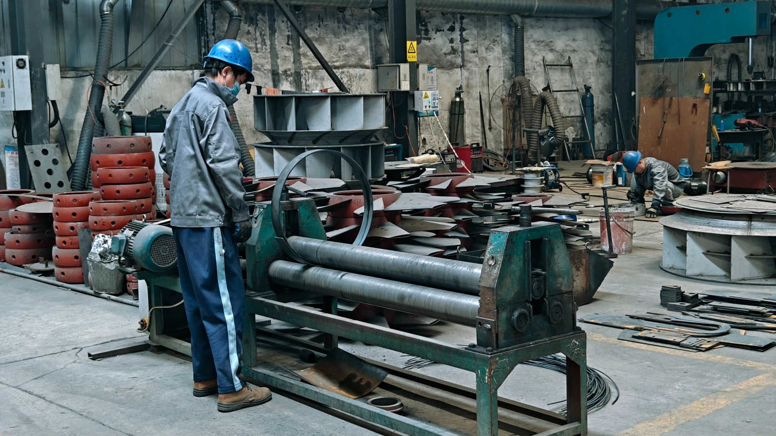
A curved metal section at the workshop rolling equipment. Other fan components are visible in the background.
Fan construction begins with an agreed configuration, not simply an outer shape. The casing, connections and supporting parts must correspond to the selected fan and its installation arrangement.
For your project, confirm the material specification, required connection geometry and any construction requirements before manufacturing documents are approved. A photograph is useful context, but the approved drawing and specification must define the equipment to be supplied.
2. A closer look at the casing opening
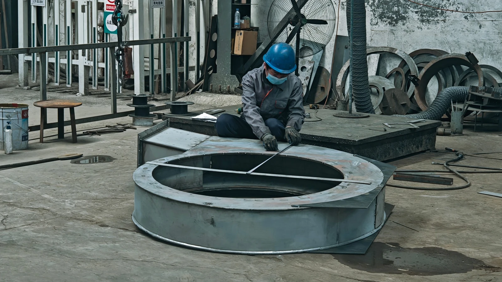
Checking a circular opening during casing fabrication.
An opening that looks suitable in a photograph may still differ from the site connection. Replacement projects therefore need measured information about the inlet and outlet, flange details, orientation and surrounding installation space.
If existing equipment must remain in place, send its general arrangement drawing or clearly labelled measurements for review. Record which dimensions are confirmed and which still need a site check. See the industrial fan GA drawing guide for the interfaces to discuss.
3. Impeller construction detail
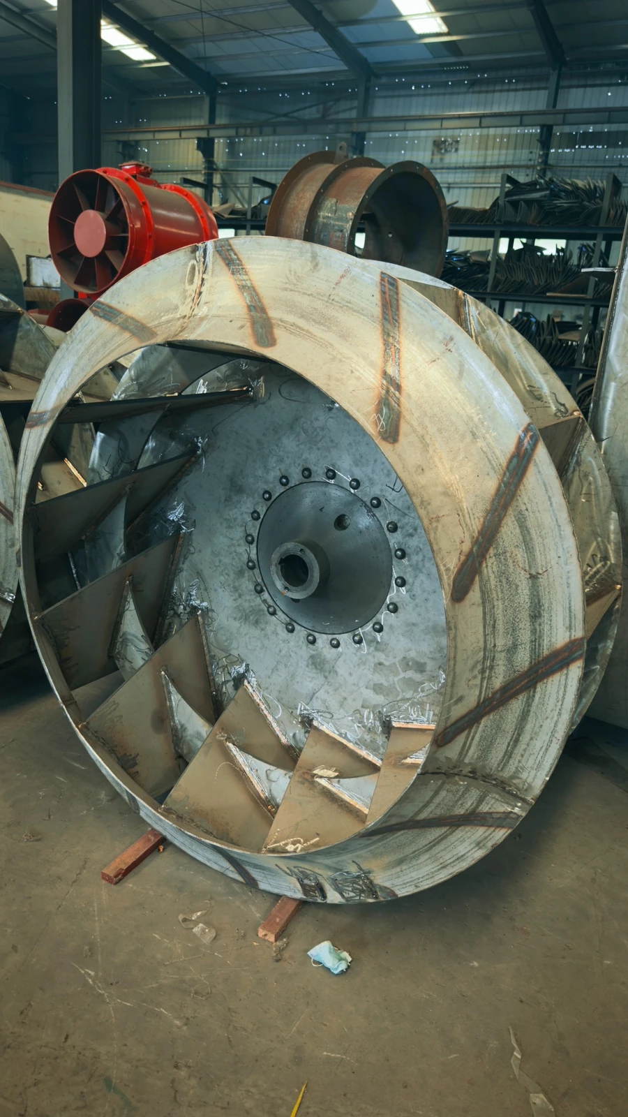
An unpainted impeller photographed separately from the complete fan. Its blades, central hub and fabricated joints are visible.
The exposed blades, hub and joints show construction details normally concealed after assembly.
When reviewing a proposed fan, connect the impeller configuration to the selected fan model, gas conditions, operating speed and performance information. If balancing or other inspection evidence is required, agree its scope and request the relevant record for the supplied assembly. The fan performance curve guide explains how to review the operating point separately from the physical appearance.
4. Motor, guard and drive-side arrangement
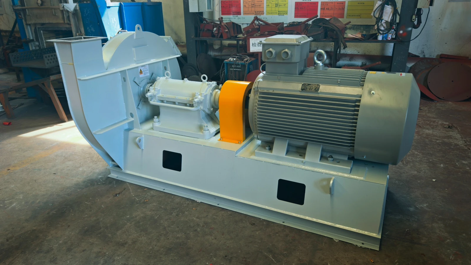
Drive-side view of an assembled centrifugal fan, showing the motor, bearing housing, guard and common supporting structure.
The drive-side layout matters when reviewing installation space, service access and the electrical scope. For the proposed equipment, confirm the fan speed, motor information, drive arrangement and installation dimensions against the approved documents.
Compare motor, bearing, guard and base options against your project requirements using the centrifugal fan drive arrangement guide.
5. Circular welded assembly before finishing
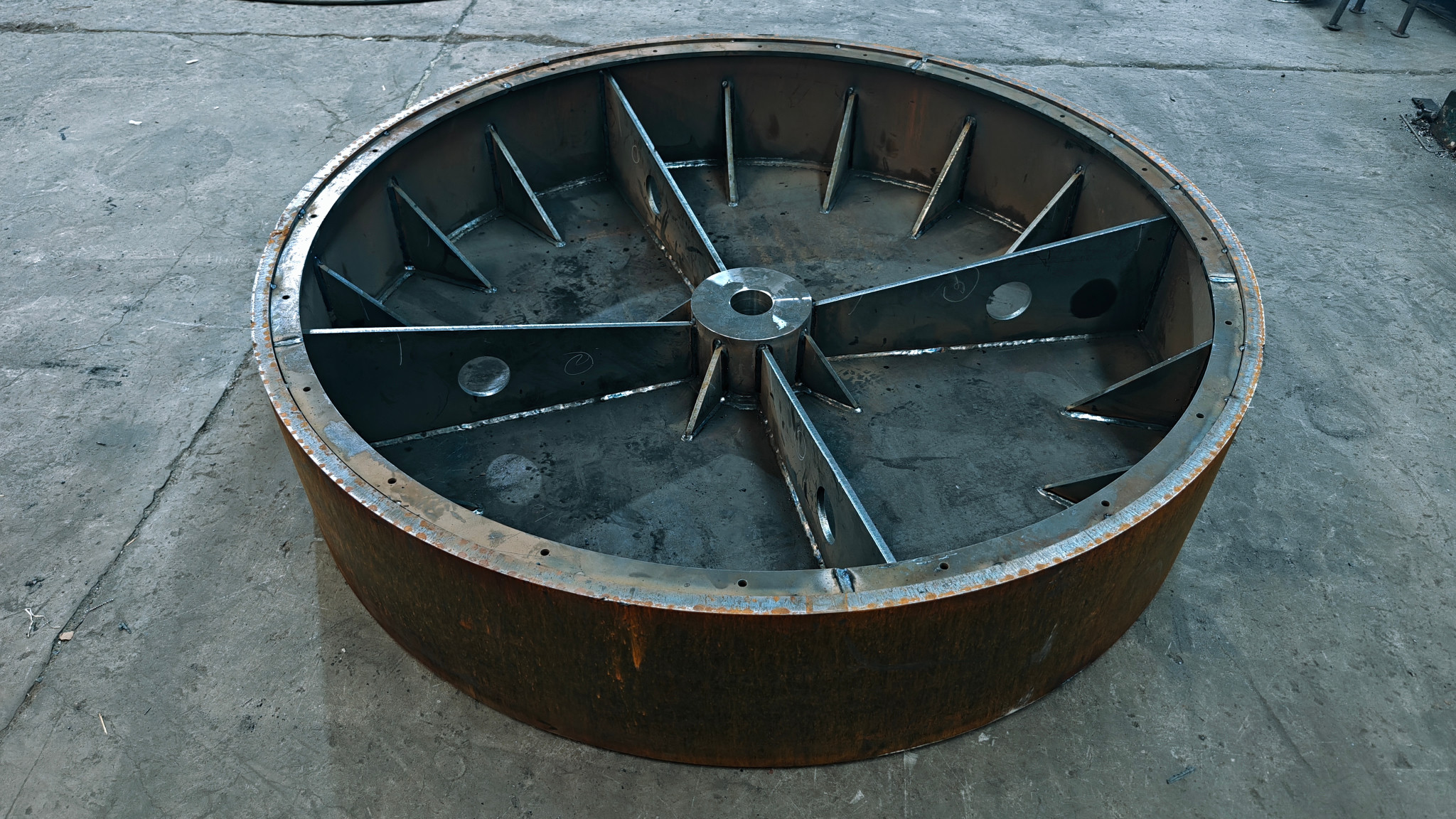
The connection pattern and central interface are key features to identify on the assembly drawing when reviewing fit and installation.
For a project review, ask for the assembly identifier and applicable drawing revision first. Then specify which feature needs confirmation, such as the connection pattern or central interface, and request the corresponding dimensioned drawing or agreed inspection record.
Use the GA interface review for installation boundaries and the controlled document package to connect photographs, drawings and records to the same equipment item.
6. Cylindrical assembly, flange and support layout
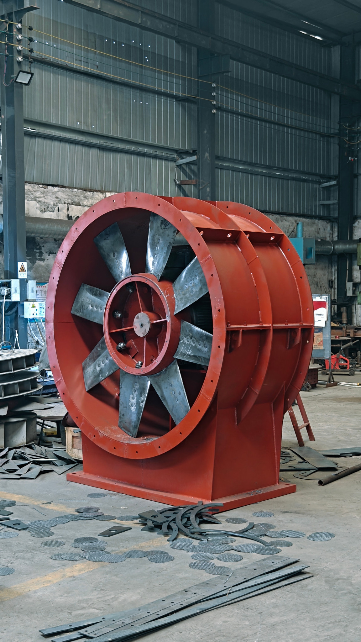
A connection review needs more than a front view. Ask for a dimensioned side view as well as the connection-face drawing so the flange position, overall envelope and support layout can be checked together. Identify the proposed airflow direction on the approved drawing rather than inferring it from the photographed blade appearance.
For a replacement enquiry, keep three sets of information separate: the existing duct interface, the existing foundation or support interface, and the proposed equipment drawing. Record which party will confirm each match and any adapter or support changes.
See the replacement photo checklist for the additional views to collect, with site access and safety precautions confirmed before photographs or measurements are taken.
Make the photographs useful to your project
When asking for a quotation or reviewing an order, identify the detail you want to discuss rather than referring only to “a fan like the picture.” Send:
- The required airflow and pressure, with their units and pressure basis.
- The medium and operating temperature, including relevant dust or corrosion conditions.
- The proposed or existing model, if known.
- Available installation drawings, labelled dimensions and electrical requirements.
- The particular construction details or project-specific records you need confirmed.
For an order in progress, request photographs tied to the relevant equipment identification and document revision. Representative workshop images help explain the manufacturing context; order-specific photographs and agreed records support review of the actual supply.
Browse centrifugal and axial fan families, review the company and manufacturing overview, or use the pre-shipment inspection checklist when preparing an order-specific acceptance scope.
Request an order-specific photograph
Use a clear reference so the supplied image can answer your project question.
- Equipment reference
- Which tag, order item or assembly?
- Detail requested
- Which component, interface or viewpoint?
- Document reference
- Which drawing number and revision?
- Question to resolve
- What needs confirmation, and by whom?
Specify the photographs and inspection records required for your order. See the technical documentation guide for record control.