
Forced Draft Duty and Selection Basis
An industrial forced draft fan system supplies controlled combustion air to boilers, furnaces, kilns and burners. The fan must deliver required airflow after losses from filters, dampers, ducts, air preheaters and burner registers.
Selection focus: fuel, firing rate, combustion-air demand, excess-air target, inlet temperature, duct and preheater loss, damper position, burner pressure and motor margin.
Typical Forced Draft Airflow Route
Airflow, system pressure and inlet temperature define the fan duty.
Specify Which Airflow the Burner Requires
A combustion-air requirement may arrive as mass flow, normal volume or standard volume. These are not interchangeable with actual cubic metres per hour at the fan inlet. Keep the original unit and reference conditions with the burner or boiler supplier’s demand.
- Demand basis: identify mass, normal, standard or actual volume; record the reference temperature, pressure and moisture basis where applicable.
- Fan inlet: record actual inlet temperature, absolute pressure or site elevation, and the required actual inlet volume or density basis.
- Preheater location: show whether heating is upstream or downstream of the fan. Do not apply a downstream burner-air temperature to an upstream ambient-air fan inlet.
The fan selection should reconcile these bases before checking the operating point. Fuel-air ratio, oxygen targets and control changes remain with the responsible combustion-system designer.
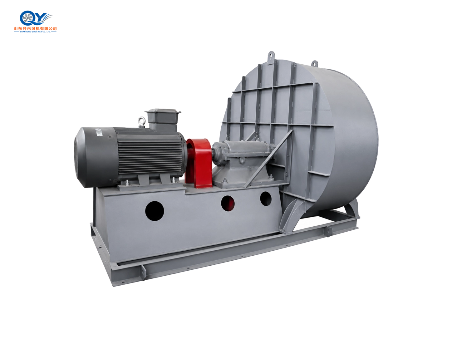
Review the G/Y4-73 product reference →
Technical basis: AMCA, Specifying Fans for Industrial Environments, flow definitions and density discussion (slides 37–40).
What a Forced Draft System Must Do
Deliver enough air for stable combustion across the firing range. Demand depends on fuel, burner, furnace load and excess-air strategy. Evaluate all inlet, control, duct, preheater and burner resistance at design airflow.
Where an induced draft fan is present, coordinate both fans to meet the furnace-pressure target.
Supply Combustion Air
Meet burner demand from low load through maximum firing.
Overcome Air-Side Resistance
Maintain flow through filters, ducts, dampers and preheaters.
Stabilize Furnace Pressure
Coordinate FD and ID control to avoid excessive positive or negative pressure.
Operate Across Load Changes
Review damper, guide-vane and speed-control options.
Forced Draft and Induced Draft Serve Different Sides
FD: Combustion-Air Supply
Push ambient or preheated air toward the burner and furnace; this is generally the cleaner air side.
- Combustion-air temperature
- Inlet and burner-side resistance
- Fuel-air ratio and combustion stability
ID: Flue-Gas Extraction
Pull gas through furnace, heat recovery, dust collection and stack while maintaining draft.
- Hot, dusty or treated flue gas
- Exhaust-side resistance
- Furnace pressure and gas removal
Why Air-Side Resistance Determines Fan Pressure
Include inlet screens, filters, silencers, dampers, ductwork, preheaters and burner registers. Operating point varies as filters load, dampers move and combustion changes.
Air Preheater
Potential major loss
Duct Length
Friction loss
Dampers / Registers
Control loss
Filters / Silencers
Inlet loss
Burner Entry
Terminal loss
Where Forced Draft Fan Pressure Loss Comes From
Review the complete air-supply route even if combustion-air demand is already known.
Inlet Screen or Hood
Restricted openings add entrance loss.
Filter and Silencer
Resistance rises as filters load or airflow increases.
Duct, Elbow and Transition
Include long ducts, reducers, expansion and bends.
Damper or Guide Vane
Control devices can add part-load resistance.
Air Preheater
Adds loss and may change air temperature and motor load.
Burner Register
Check terminal resistance with burner supplier or project data.
Combustion Load Changes Require Airflow Control
Select fan and control method to support startup, low load and maximum firing.
Inlet Damper
Simple control, with throttling loss at part load.
Inlet Guide Vanes
Part-load control on suitable configurations, subject to model review.
Variable Speed
Matches speed to demand where motor and drive system permit.
FD / ID Coordination
Maintain airflow while keeping furnace pressure at project target.
Parameters Required for Forced Draft Fan Selection
Combustion and Furnace
- Boiler, furnace, kiln or burner type
- Fuel and maximum firing rate
- Required combustion airflow
- Excess-air target or oxygen control
- Furnace-pressure target and ID arrangement
- Normal and maximum inlet-air temperature
- Operating time and load range
Air-Side and Installation
- Required static or total pressure
- Filter, silencer and screen resistance
- Duct length, diameter, elbows and transitions
- Preheater and burner-register resistance
- Damper, guide-vane or speed control
- Motor voltage, frequency, phase and protection
- Rotation, outlet angle, space and quantity
Forced Draft Fan Model Direction
Select by actual combustion-air demand, system pressure, inlet temperature, control and installation.
Boiler forced- or induced-draft matching against duty.
View product page →Medium and larger boiler draft with confirmed pressure.
View product page →Boiler air supply with installation and continuous-duty review.
View product page →Higher-pressure combustion-air systems with long ducts.
View product page →Larger airflow and higher pressure at confirmed point.
View product page →High-pressure combustion and process-air direction.
View product page →Additional Higher-Pressure Options
Screen these series only where the documented airflow–pressure envelope matches the confirmed duty.
New Combustion-Air Systems and FD Fan Replacements
New System
Calculate maximum combustion-air demand and pressure loss throughout the air route.
- Fuel, burner and firing data
- Airflow and full-load resistance
- Preheater and controls
- Motor, installation and FD / ID coordination
Replacement
Compare original duty with furnace load, duct changes, damper, preheater and combustion control.
- Fan and motor nameplates
- Airflow, pressure, speed and power
- Air-side components and connection dimensions
- Low oxygen, high power, noise or vibration
Available Configuration Directions
Ambient or Preheated Air
Confirm inlet temperature and motor load.
Damper or Speed Control
Match load range and energy requirements.
Rotation and Outlet
Match discharge to air duct layout.
Drive Arrangement
Direct or coupling depends on size, speed and heat.
Motor and Power
Confirm voltage, frequency, protection and start.
Base and Isolation
Consider foundation, flexible joint and vibration.
High inlet temperature, explosive atmosphere, corrosive air, frequent cycling and special burner control need separate review.
Boiler Fan Families and Technical Guides
Boiler Forced Draft Fans
Open page →Boiler Induced Draft Fans
Open page →High-Temperature Industrial Fans
Open page →Boiler Fan Selection Guide
Open page →FD Fan vs ID Fan
Open page →FAQ About Industrial Forced Draft Fan Systems
What does a forced draft fan do?
It supplies combustion air at enough flow and pressure to overcome inlet filters, dampers, ducts, preheaters and burner registers.
How is it different from an induced draft fan?
FD pushes combustion air on the clean side; ID extracts flue gas through furnace, treatment and stack.
How is combustion airflow determined?
Fuel, firing rate, excess-air target, burner design, load and control strategy determine demand. Confirm maximum duty and resistance.
How does an air preheater affect selection?
It adds resistance and may change air temperature; include both in fan performance and motor-load review.
Can a high-pressure centrifugal fan be used?
Yes, where airflow, pressure, temperature and conditions match the documented operating range.
Which model should be considered?
GY4-73, GY5-51 and GY6-41 are draft directions. Higher-resistance duties can be screened across high-pressure series after confirming the actual duty point.
Send Your Forced Draft Parameters
Furnace or boiler, fuel, firing rate, combustion airflow, pressure loss, inlet temperature, preheater, control method, voltage and quantity.