
Industrial Fan Manufacturing · Zibo, China
QIYUE FAN industrial fan manufacturer
Menu
Industrial fan power calculation original article image
QIYUE FAN · TECHNICAL ARTICLES

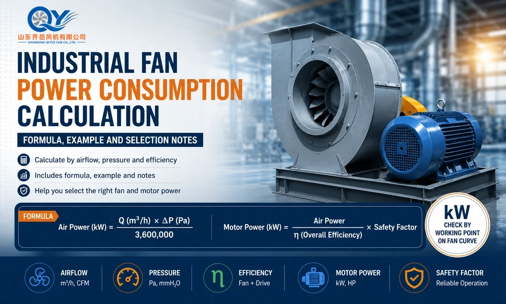
Industrial Fan Power Consumption Calculation: Formula, Example And Selection Notes

Follow the Power Boundaries

Read from electrical supply to useful air power. Keep the measurement boundary visible when comparing figures.

  1. 01 / Electrical input

    State whether the electrical input is measured at the motor terminals or upstream of a controller. Include controller losses only when that controller is inside the declared boundary.

  2. 02 / Motor shaft output

    Mechanical power delivered by the motor after its losses. This operating output is distinct from the motor’s nameplate rated output capacity.

  3. 03 / Fan shaft input

    Mechanical power delivered to the fan. Account for the selected transmission where present; do not assume every configuration has the same drive losses.

  4. 04 / Air power

    Total air power is based on fan total pressure. If using a static air-power basis instead, pair it with fan static efficiency. Do not mix these definitions.

Separate capacity decision

Any justified motor-sizing margin belongs in the capacity review. It is not another energy-loss stage and must not be counted again inside an efficiency allowance.

Conceptual power-boundary map, not measured performance. Read the numbered stages in order; apply the boundaries, component losses and pressure/efficiency definitions for the selected configuration. No loss proportions are represented.
Power Calculation Framework

Four Inputs That Control Motor Power

Separate air power, fan shaft power, required motor mechanical output and electrical input. Motor selection follows the verified operating envelope; a nameplate rating is not the actual electrical consumption.
Power Factor 01
Airflow
Larger m³/h or CFM means the fan must move more air through the system.
Power Factor 02
Pressure
Duct resistance, filters, elbows, dampers and outlet loss increase pressure demand.
Power Factor 03
Efficiency
Fan efficiency and drive efficiency affect the difference between air power and motor power.
Power Factor 04
Safety Margin
A proper margin helps avoid overload but excessive oversizing wastes energy.
Calculation Basics

Basic Industrial Fan Power Formula

For a preliminary low-compressibility estimate, use airflow at the fan inlet condition and a declared fan pressure basis. Divide total-pressure air power by fan total efficiency, or static-pressure air power by fan static efficiency, to estimate fan shaft power. Do not mix the two efficiency definitions.

Confirm motor rating against the selected fan power curve, operating range, inlet gas condition, transmission, starting and control requirements. Any selection allowance must be stated separately; it is not an efficiency or automatically a motor service factor.

Before using the formula, confirm the required duty point with the Airflow & Pressure guide.
Formula 01
Air Power kW = Q × ΔP ÷ 3,600,000
Q = inlet-condition volume flow in m³/h | ΔP = declared fan total or static pressure in Pa. Match the efficiency to this pressure basis.
Formula 02
Motor mechanical output required ≈ Air Power ÷ (Fan Efficiency × Transmission Efficiency)
Use efficiencies at the stated duty. Apply each loss only once. Motor electrical input additionally depends on motor efficiency; supply-side input also includes controller losses where applicable. Keep any motor-sizing allowance separate from actual operating power.
Calculation Example

Example: 18,000 m³/h and 2,200 Pa Industrial Dust Exhaust

Illustrative arithmetic only: assume inlet-condition flow of 18,000 m³/h and fan total pressure of 2,200 Pa. Assume fan total efficiency × transmission efficiency = 0.65, excluding motor/controller losses. Apply a separate illustrative motor-sizing multiplier of 1.15. Neither assumed value is a recommended design default.
18,000
Airflow m³/h
2,200
Pressure Pa
0.65
Fan × Transmission Efficiency
1.15
Illustrative Sizing Multiplier

Swipe the table sideways to view all columns.

Step Calculation Result Selection Meaning
Air Power 18,000 × 2,200 ÷ 3,600,000 11.0 kW Theoretical air power only
Before Margin 11.0 ÷ 0.65 16.9 kW Estimated motor mechanical output, before sizing allowance
After Illustrative Sizing Allowance (11.0 ÷ 0.65) × 1.15 19.5 kW mechanical-rating check Not electrical input; no motor rating approved by this example
Selection note: the arithmetic gives 11.0 kW air power, about 16.9 kW motor mechanical output and about 19.5 kW after the illustrative allowance, calculated from the unrounded 11.0 ÷ 0.65 result. Select an available motor only after checking the full required operating range and project conditions. Do not use the allowance or nameplate rating as running electrical power. Energy use in kWh depends on electrical input and time at each operating condition.
Power Consumption Factors

What Affects Industrial Fan Power Consumption?

Airflow Demand
Oversized airflow increases motor load, energy cost and noise.
System Resistance
Long ducts, elbows, filters, baghouses and silencers all increase pressure loss.
Fan Efficiency
A fan far from its efficient range may consume more power and create unstable airflow.
Air Density
Hot gas, altitude and special gas density can change the fan operating point.
Dust Load
Dust collectors and dirty ducts may increase resistance during operation.
Control Method
VFD speed control may reduce energy use when airflow demand changes.
Temperature & Density
Hot gas changes density and power demand
Confirm the real gas temperature and density basis before using catalog power values.
Read Temperature Guide →
Pressure Basis
Use the correct static or total pressure value
If the pressure basis is wrong, the calculated motor power will also be wrong.
Read Pressure Guide →
Fan Selection Path

Power Review Should Follow the Real Working Point

Step 01
Application
dust, workshop, boiler or tunnel
Step 02
Airflow
m³/h or CFM demand
Step 03
Pressure
static or total pressure
Step 04
Fan Curve
efficient operating point
Step 05
Motor kW
voltage and margin
Important: if static pressure is not yet known, do not reverse-engineer it from motor kW. Use the Static Pressure Unknown guide and establish the system resistance first.
Product Direction

Which QIYUE FAN Product Direction Should Be Checked?

Product Family
Centrifugal Fans
For duct systems, dust collectors, boiler draft and medium-to-high pressure airflow.
Product Family
Axial Flow Fans
For large airflow and lower pressure ventilation systems.
Application Product
Dust Collection Fans
For baghouses, filter resistance and dust-laden exhaust airflow.
High-Pressure Product
9-19 High Pressure Fan
For forced draft, pneumatic conveying and higher-resistance duties.
Avoid Power Waste

Common Selection Mistakes That Increase Power Cost

Mistake 01
Only Checking Motor kW
A 22 kW fan from one model is not equal to another 22 kW fan. The curve and operating point must be checked.
Mistake 02
Ignoring Duct Resistance
If elbows, filters and long ducts are not included, the selected fan may not deliver required airflow.
Mistake 03
Oversizing the Fan
Too much margin can increase noise, vibration, damper loss and long-term energy consumption.
Mistake 04
Using Clean-Air Data
Dust, temperature and corrosion conditions may require different materials, structures or motor positions.
Technical Next Steps

Continue With Duty Point, Pressure and Speed Review

Power calculation should sit inside the wider fan-selection process, not be used as a standalone shortcut.
Main Selection Route
Industrial Fan Selection Center →
Review airflow, pressure, medium, temperature, layout and electrical data together.
Duty Point
Industrial Fan Airflow and Pressure
Establish the required airflow and pressure before calculating power.
Operating Point
Fan Performance Curve
Check airflow, pressure, absorbed power and operating point.
Pressure Basis
Static vs Total Pressure
Avoid mixing pressure definitions during power calculation.
Speed
Motor Poles, RPM and 50Hz/60Hz
Understand how motor frequency and speed affect fan performance.
FAQ

FAQ About Industrial Fan Power Consumption

Can I select a fan only by motor power?
No. Motor power is one result of selection. Airflow, pressure, speed, efficiency, system resistance, medium condition and performance curve should be checked together.
Why does the same airflow need different motor power?
Because pressure and system resistance may differ. A long duct system, bag filter or high-resistance equipment may require much higher pressure than simple room ventilation.
Does a centrifugal fan consume more power than an axial fan?
Not always. Power depends on airflow, pressure and efficiency. Centrifugal fans are often used for higher pressure, while axial fans are often used for large airflow and lower pressure.
How can I reduce industrial fan energy consumption?
Avoid oversizing, reduce unnecessary duct resistance, select a fan near its efficient range, maintain filters and ducts, and review VFD speed control when airflow demand changes.
Should baghouse filter resistance be included in power calculation?
Yes. Review clean and loaded-filter duty cases. If the same airflow must be maintained, greater required pressure increases air-power demand. With unchanged fan speed, added resistance can instead shift airflow and absorbed power along the fan curve; motor power does not necessarily increase.
What data should I send for motor power review?
Send airflow, static pressure or total pressure, fan speed, medium temperature, duct layout, filter resistance, dust or gas condition, voltage, frequency and quantity.

Technical references: AMCA 211, Annex H, power boundaries and AMCA guidance on fan power curves. These references do not certify this calculation or any QIYUE product.

Send Your Operating Conditions

Airflow, pressure, gas medium, temperature, voltage and quantity.

REQUEST A QUOTE →