Conveying Airflow and Selection Inputs
An industrial pneumatic conveying air system uses controlled airflow to transport powder or granular material through a pipeline. The fan must provide sufficient clean-air volume and pressure to maintain conveying velocity through the complete route.
Selection focus: material type, bulk density, particle size, hardness, moisture, feed rate, pipeline length, vertical lift, number of bends, conveying velocity, separator resistance and system leakage.
Typical Positive-Pressure Conveying Route
Air passes through the fan before material enters the pipeline. The air and material mixture then travels to a separator and final filter.
What a Pneumatic Conveying Air System Must Do
The air system must maintain enough velocity to suspend and transport the material without excessive settling, blockage or product damage. The fan must overcome pressure loss from the intake, pipeline, bends, vertical lift, material pickup, separator, receiver and final filtration equipment.
The fan should preferably handle clean air. When material or dust passes through the impeller, wear, buildup, imbalance and maintenance requirements can rise significantly.
Generate Conveying Airflow
Provide the air volume needed to carry material through the pipeline.
Overcome Total Pipeline Resistance
Maintain pressure through bends, vertical lifts, valves and separation equipment.
Prevent Settling and Blockage
Keep velocity above the project requirement throughout the conveying route.
Protect Fan and Product
Keep abrasive material away from the fan where possible and control conveying velocity.
Positive-Pressure and Negative-Pressure Systems
Fan position changes leakage direction, material pickup and whether the fan handles clean or contaminated air.
Positive-Pressure Conveying
The fan supplies clean air before the feeding point and pushes the mixture toward the receiver.
- Fan remains on the clean-air side
- Delivery to one or more receiving points
- Feeding device controls air leakage
Negative-Pressure Conveying
The system pulls material toward a receiver. Place the fan after effective separation and filtration whenever possible.
- Collect from multiple pickup points
- Leakage draws air inward
- Separator and filter protect the fan
Why Pipeline Length, Bends and Material Loading Matter
Pressure loss rises with pipeline length, vertical lift, bends, valves, pickup devices and material loading. The separator, receiver and final filter also add resistance. Select the fan against the full route at the required feed rate; pipe diameter alone cannot determine capacity.
Pipeline Length
Friction loss
Material Loading
Two-phase loss
Bends / Valves
Local loss
Vertical Lift
Elevation demand
Separator / Filter
Terminal loss
A Larger Pipe Does Not Preserve Air Velocity
For a circular section, average gas velocity is actual volumetric flow divided by cross-sectional area: v = Q / A, with Q in m³/s and A in m². Use the gas volume at that pipe section’s actual pressure and temperature, not an unspecified standard-volume number.
Illustrative calculation only: hold actual flow at 0.6283 m³/s (approximately 2,262 m³/h) and use the internal diameters below. This is a geometry comparison, not a recommended conveying velocity or a QIYUE performance guarantee.
Area ≈ 0.03142 m²
Average velocity ≈ 20.0 m/s
Area ≈ 0.07069 m²
Average velocity ≈ 8.89 m/s
Bars share a zero baseline and 20 m/s full scale. A 50% diameter increase gives 2.25 times the area, leaving about 44.4% of the original average velocity at the same actual flow. Rounding is shown.
This comparison holds flow constant; a real pipe change may also shift the fan operating point. It does not predict solids transport, pressure loss or capacity in tonnes per hour. The system designer must confirm the material-specific conveying regime and operating range.
Coperion’s pneumatic conveying overview notes that high air velocity can cause material degradation or wear. Therefore, “more air” is not automatically the right remedy for a blocked or low-capacity line. Review the material and system before changing speed, pipework or feed rate.
The Material Determines Velocity, Wear and Blockage Risk
Material properties affect air volume, conveying velocity, pipe diameter, separator design and whether direct contact with the fan is acceptable.
Bulk Density
Heavier material generally requires greater conveying energy and may reduce system capacity.
Particle Size
Particle distribution influences suspension velocity, separator efficiency and pipe wear.
Hardness and Abrasion
Abrasive particles increase wear at bends, valves, separators and any fan exposed to the material.
Moisture and Stickiness
Moist or sticky material can build up in pipelines, feeders, separators and fan inlets.
Centrifugal Fans Suit Specific Conveying Pressure Ranges
Clean-air centrifugal fans can be reviewed for low-pressure and some medium-pressure dilute-phase systems. Confirm the actual duty point before choosing an air source.
Suitable Project Direction
- Low-pressure dilute-phase conveying
- Clean-air positive-pressure supply
- Clean-side suction after separator and filter
- Powder or granules with confirmed pipeline loss
Requires Different Equipment Review
- Dense-phase high-pressure conveying
- Very long-distance heavy material transport
- High compression-ratio or pulsed conveying
- Highly abrasive material passing through the fan
Parameters Required for Pneumatic Conveying Fan Selection
Complete material, pipeline and operating information helps determine series, airflow, pressure, motor power and arrangement.
Material and Capacity
- Material name and composition
- Bulk density and feed rate
- Particle size distribution
- Hardness and abrasiveness
- Moisture, stickiness and temperature
- Required conveying capacity per hour
- Fragility or contamination limits
Pipeline and Fan
- Pipeline diameter and total length
- Horizontal and vertical distance
- Number and radius of bends
- Pickup, feeder and discharge arrangement
- Cyclone, receiver and filter resistance
- Required airflow and pressure if available
- Motor voltage, frequency, installation and quantity
Once these inputs are assembled, follow the pneumatic conveying fan selection workflow to connect material and route information to actual airflow, system pressure and a matching fan operating point.
Coordinate the Fan Package with the Conveying Line
A clear supply schedule connects equipment selection, installation and system acceptance.
Fan Package
Specify the fan, motor, drive, base and required accessories, with the selected airflow–pressure point and installation drawing.
Conveying Equipment
Define the feeder, pipeline, receiver, separator and filter scope. Assign responsibility for the overall conveying calculation and process layout.
Site Interfaces
Coordinate flange dimensions, supports, electrical supply, control integration and installation space against the current project drawings.
Acceptance
Agree fan performance and complete-line throughput separately, using the specified material, route and operating conditions.
Quotation schedule: equipment item · supplier · drawing revision · included accessories · acceptance requirements.
Pneumatic Conveying Fan Model Direction
These product pages provide model directions. Final selection depends on material, conveying capacity, airflow, pressure and pipeline resistance.
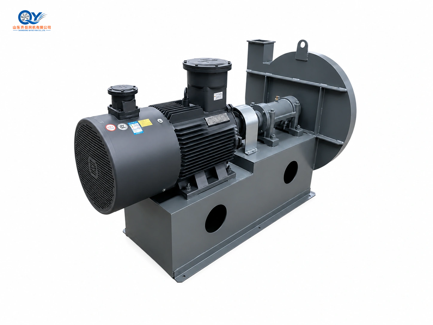
Motor, drive assembly and casing on a common base. For positive-pressure conveying, the fan supplies air upstream of material injection; the feeder, pipeline, receiver and filter complete the system.
Select the fan against the required airflow–pressure point and material-handling conditions.
Higher-pressure clean-air supply for long pipelines, multiple bends or notable separator resistance.
View product page →Larger air volume and higher system resistance at a confirmed operating point.
View product page →High-pressure air supply before material enters the pipeline.
View product page →Compact or medium-capacity duties requiring higher pressure, subject to route and material review.
View product page →Large-volume, lower-pressure centralized air supply or receiving-side ventilation.
View product page →Additional Clean-Air Fan Series
Review these documented series when the fan remains on the clean-air side and its airflow–pressure range matches the duty.
Dense-phase or very-high-pressure conveying may require a blower or another air-source solution. See Material Handling Fans for material and abrasion considerations.
New Conveying Lines and Existing-System Upgrades
New System
Evaluate material, capacity, pickup method, pipe route and receiving equipment before selecting the fan.
- Material test data and conveying rate
- Complete pipe route and elevation
- Feeder, separator and filter arrangement
- Fan duty, motor, control and redundancy
Upgrade
Compare current fan duty with feed rate, pipe changes, blockage points, leakage, separator condition and product properties.
- Existing fan and motor nameplates
- Airflow, pressure, speed and power
- Pipeline, feeder and separator arrangement
- Current blockage, low capacity, wear or product damage
FAQ About Industrial Pneumatic Conveying Air Systems
What type of conveying is covered here?
Low-pressure and some medium-pressure dilute-phase systems with material suspended in moving air. Dense-phase or high-pressure systems need a separate air-source review.
Should material pass through the fan?
For abrasive, hard or valuable material, keep the fan on the clean-air side where possible. Direct passage through the impeller can cause wear and imbalance.
What determines the required pressure?
Pipe length and diameter, bends, vertical lift, pickup device, feed rate, material loading, separator resistance and required conveying velocity.
Why is material information needed?
Bulk density, particle size, hardness, moisture, stickiness and fragility affect velocity, pipe wear, blockage and product damage.
Can a centrifugal fan replace a positive-displacement blower?
Only if the required airflow and pressure fall within a suitable fan operating range. Dense-phase and high-pressure service generally needs another air source.
Which QIYUE FAN model should I consider?
9-19, 9-26, 8-09 and 9-12 are higher-pressure clean-air directions; 4-2×72 is a large-volume lower-pressure direction. Select against the actual operating point and full route.
Send Your Pneumatic Conveying Parameters
Material, capacity, bulk density, particle size, pipe route, bends, separator resistance, airflow, pressure, voltage and quantity.