
Industrial Drying Oven Hot Air Circulation System
Hot Airflow, Temperature and Pressure
An industrial drying oven hot air circulation system delivers heated air through the chamber, removes moisture from the product and returns part of the air for recirculation. Fan selection must support airflow uniformity, temperature and total system resistance.
Selection focus: chamber size, product loading, evaporation rate, drying temperature, fresh-air ratio, return-air ratio, heater resistance, duct layout, filters, moisture exhaust and fan position.
Typical Hot Air Circulation Route
A portion of the return air recirculates; controlled exhaust removes moisture and fresh air makes up the balance.
What a Hot Air Circulation System Must Do
Distribute heated air evenly across the product, maintain the required temperature and carry evaporated moisture away from the surface. Recirculation can improve energy efficiency, while controlled exhaust limits humidity.
Fan position matters: before the heater it handles cooler air; after the heater it must suit the actual hot-air temperature.
Move Heated Air
Maintain sufficient air velocity around all product surfaces.
Maintain Temperature Uniformity
Reduce hot spots, cold zones and uneven drying.
Remove Moisture-Laden Air
Balance recirculation, fresh-air intake and controlled exhaust.
Overcome System Resistance
Maintain airflow through heaters, filters, ducts, dampers and product loading.
Supply Air, Return Air and Moisture Exhaust Must Be Balanced
Circulation supports heat transfer; exhaust removes humid air to maintain drying performance.
Supply Air
Heated air reaches all product zones with adequate velocity and temperature.
Return Air
Return paths avoid short-circuiting and draw air across the chamber.
Moisture Exhaust
Remove humidity at a rate that supports evaporation without excessive heat loss.
Fresh Air Makeup
Replace exhausted air and control humidity and process atmosphere.
Why Heater, Filter and Product Resistance Matter
The fan must maintain required airflow after losses from heat exchangers, filters, ducts, dampers, perforated plates, product racks and return-air paths. Resistance can change as filters load and product blocks airflow; select against production conditions, not an empty chamber.
Heat Exchanger / Heater
Potential major resistance
Product Loading
Variable loss
Duct and Return Path
Friction loss
Filters / Screens
Maintenance-dependent loss
Dampers / Outlets
Control loss
Cool-Side and Hot-Side Fan Arrangements
Position determines the temperature handled by the impeller, shaft, bearings and drive.
Cool-Side Fan
Before the heater or in a cooler return section; reduces thermal stress on the fan and motor.
- Lower-temperature inlet air
- Simpler bearing and motor protection
- Heater loss remains in pressure calculation
Hot-Side Fan
Handles heated or moisture-laden air after the heater or chamber; temperature and material configuration need confirmation.
- Elevated inlet-air temperature
- Temperature-aware shaft and bearing design
- Review moisture and vapor conditions
Quote the Air Paths Separately
A circulation duty and a moisture-exhaust duty are not interchangeable. ASHRAE’s industrial drying chapter treats circulating airflow, makeup/exhaust airflow and heat balance as distinct calculation inputs. It also explains the trade-off between recirculation, heat loss and moisture pickup. There is no single recycle percentage appropriate to every product or operating stage.
Across the product
Identify the supply and return route, product/rack loading and the air condition at the circulation fan. Attach the relevant path resistance or measured duty, not the total exhaust requirement.
Out of the system
Identify the moisture or vapor outlet route, discharge boundary and exhaust fan if present. Provide the process designer’s required exhaust duty and air condition for the stated operating case.
Into the system
Identify where replacement air enters and whether a separate supply fan is present. Confirm its own route and boundary; do not assume three separate fans are required by this diagram.
Process-air roles for the RFQ.
A separate record for each selected fan
Keep wet- or dry-basis product moisture figures clearly labelled. For batch equipment, identify the stage represented by each case instead of assuming a single moisture load throughout the cycle. The process designer must establish drying, ventilation and safety requirements before fan selection is finalized.
Safety boundary: solvent vapor, combustible dust or other hazardous duty requires project-specific specialist review. Do not reduce exhaust, change recirculation settings or bypass interlocks on the basis of this page.
Use the gas-condition and flow-basis guide for each fan duty, and keep the motor’s ambient conditions separate from the process-gas temperature.
Reference: ASHRAE 2019 HVAC Applications, Chapter 31: Industrial Drying Systems, sections 2–3. Agree the circulation, exhaust and makeup-air duties with the process designer.
Parameters Required for Drying-System Fan Selection
Complete chamber, product, temperature and airflow information helps determine series, motor power, temperature configuration and installation.
Drying Process
- Product type and loading quantity
- Initial and target moisture content
- Drying temperature and time
- Chamber dimensions and rack arrangement
- Heating method and heat-source location
- Fresh-air and moisture-exhaust requirement
- Batch or continuous mode
Airflow and Fan
- Required airflow and pressure
- Fan inlet and outlet air temperature
- Heater and filter resistance
- Duct length, branches, dampers and outlets
- Recirculation and exhaust-air ratio
- Motor voltage, frequency, phase and protection
- Rotation, outlet angle, installation and quantity
Drying and Hot Air Circulation Fan Direction
Select against airflow, temperature, pressure, fan position and installation conditions. Hot-side duty needs separate temperature confirmation.
Clean-air circulation and supply where airflow, temperature and resistance match.
View product page →Medium-pressure drying-air circulation with known duct and heater loss.
View product page →Large-volume, lower-pressure air circulation with temperature and installation review.
View product page →Large-volume centralized system, wide chambers or common plenums.
View product page →Higher-resistance lines with long ducts, narrow nozzles, filters or exchangers.
View product page →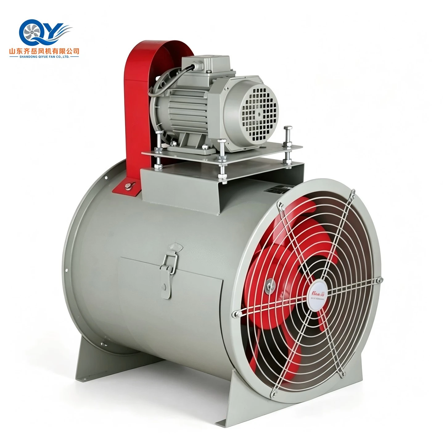
An Axial Direction for Lower-Resistance Circulation
The GD30 range is also positioned for drying and heated-process circulation where the required airflow and pressure fit its documented operating points. Compare this axial option with the centrifugal ranges against the required operating point.
Check the resistance of the loaded chamber, heater, filter and return route. A high airflow figure at low pressure is not evidence that the same fan can overcome a high-resistance drying system.
Specify normal and maximum fan-inlet temperature, construction and any solvents in the airstream so temperature and medium compatibility can be assessed.
New Drying Systems and Existing Oven Upgrades
New System
Consider airflow, heater capacity, recirculation, moisture exhaust and chamber distribution together.
- Product load and drying target
- Chamber, rack and air-distribution layout
- Heater, filter and duct resistance
- Fan position, control, motor and maintenance access
Upgrade
Compare fan duty with product loading, filters, heater condition, leakage, recirculation and temperature distribution.
- Fan and motor nameplates
- Airflow, pressure, speed, power and temperature
- Chamber, heater and return-air arrangement
- Uneven drying, long cycle, noise or vibration
Available Configuration Directions
Review configuration against fan series, airflow, pressure, temperature, moisture and factory confirmation.
Cool-Side or Hot-Side
Choose location by actual inlet temperature and moisture.
Recirculation and Exhaust
Dampers balance energy use and humidity removal.
Rotation and Outlet
Discharge matches the heater, chamber and return duct.
Drive Arrangement
Direct, coupling or belt drive depends on speed, heat, maintenance and space.
Motor and Power
Confirm voltage, frequency, phase, protection and starting method.
Flexible Joint
Allow vibration isolation and thermal expansion where needed.
High temperature, solvent vapor, corrosive moisture, explosive atmosphere and hygiene requirements need separate material and safety review.
FAQ About Industrial Drying Oven Hot Air Circulation
What does a hot air circulation fan do?
It moves heated air through the chamber, across the product and back through the return path. Stable airflow supports uniform temperature and moisture removal.
Should the fan be installed before or after the heater?
Both arrangements are possible. The cool-side fan handles lower temperature; a hot-side fan needs appropriate materials, bearings and drive arrangement.
How is drying airflow determined?
Chamber size, product loading, evaporation rate, drying time, air temperature, allowable variation and recirculation ratio all affect airflow.
Why is recirculation ratio important?
Recirculation can improve energy efficiency, but fresh-air makeup and moisture exhaust remain necessary to control humidity.
When might a higher-pressure fan be needed?
Long ducts, heat exchangers, filters, narrow air outlets, perforated plates or high-resistance loading can raise pressure demand.
Which model should I consider?
4-72, 4-79 and 4-68 are common clean-air directions; 4-2×72 suits larger volumes, while 9-19 can be reviewed for higher resistance. Confirm temperature and the duty point.
Send Your Drying-System Parameters
Product, chamber size, temperature, airflow, pressure, heater loss, recirculation ratio, voltage and quantity.